
¥ 价格面议
¥ 价格面议
¥ 价格面议

¥ 价格面议
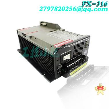
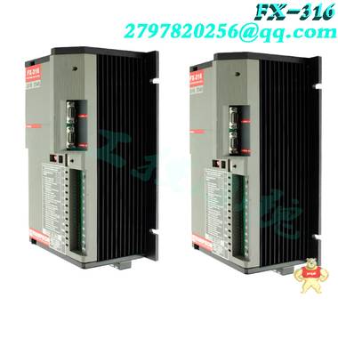
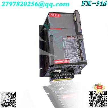
易卖工控网(www.ymgk.com)提供”A6120工业轴相对振动监测器”,产品详情:品牌/厂家:Emerson、型号:A6120、成色:全新、货期:现货 1天内发货、保修:180天,更多产品详情就上易卖工控网。
PLC是一款功能强大的大型模块化控制器,其总内存大小为256K至2M,用户逻辑大小为8K至2.9M(7M w/PCMCIA卡),寄存器大小为10K至128K,扩展寄存器为96K(7M w/PCMCIA卡。 Quantum PLC产品线支持热备用、本地、远程和分布式I/O配置,包括双电缆和多个网络选项。
140CPU4342U Quantum Unity本机处理器800 KB。与现有Quantum处理器140CPU4342A相同的CPU,此U CPU为Unity原生。Unity操作系统已下载,该CPU已准备好与Unity Pro软件一起使用。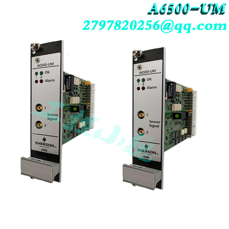 140CPU31110 Unity Quantum处理器,带400 Kb处理器
140CPU65150 Unity Quantum处理器,512 Kb内存,用于程序和未分配数据,可通过PCMCIA扩展至7 MB;和以太网
140CPU65160 Unity Quantum处理器,768 Kb内存,用于程序和未分配数据,可通过PCMCIA扩展至7 MB;和以太网
140CPU67160 Unity Quantum热备用处理器,带768/7168K。Unity Quantum热备用处理器,带热备用光纤通信端口
490NOR00003光缆3m。MTRJ/MTRJ电缆,用于通过光纤端口将两个热备用Unity处理器连接在一起。
490NOR00015光缆15m。MTRJ/MTRJ电缆,用于通过光纤端口将两个热备用Unity处理器连接在一起
140CPU65160S基于140CPU65160的独立CPU
基于140CPU67160的140CPU67160S热备用CPU
140CPU11302量子控制器、256k RAM、8K用户逻辑、10K寄存器、1个ModBus和1个ModBusPlus端口,
140CPU11303量子控制器、512k RAM、16k用户逻辑、10K寄存器、1个ModBus和1个ModBusPlus端口
140CPU4342A量子控制器,486,2M SRAM,2个ModBus端口,1个ModBus Plus。钥匙开关至启动/内存保护/启动控制器
140CPU53414B量子控制器,2.5 MRAM,2个ModBus端口,1个ModBus Plus。数学协处理器。启动/内存保护/启动控制器按键开关
Modicon PLC施耐德PLC Telemecanique PLC
The IC697PWR748 is a 90W 48 VDC Power Supply Module by GE Fanuc for the 90-70 Series. It has three output voltages (+5 VDC output up to 18 amps, +12 VDC output up to 1.5 amps, and -12 VDC output up to 1 amp) totaling 90 watts. The module features slide-in rack mount construction and two rack operation from a single power supply. This power supply is equipped with electronic short circuit overcurrent protection provided on a 5 volt bus.
This particular unit plugs into a 48-pin backplane-mounted connector (see leftmost slot in the rack). It delivers +5 volt, +12 volt, and -12 volt power. Logic level sequencing signals to the backplane. The IC697PWR748 power supply module can be used in a single rack application or, if the user prefers, it can provide power to a second rack. If the latter is chosen, it is important that the total load is within the supply rating.
Interconnection to the second rack is by way of a prewired cable (IC697CBL700). The power supply output will ride through a 10 ms total loss of input power at full load. Protection is delivered for overcurrent and overvoltage fault conditions. The power supply comes standard with an electronic overvoltage protection circuit which will clamp the output if the 5 V bus exceeds 6.7 volts. External overvoltage on the output will not cause the power supply fuse to open, but if an internal fault in the power supply caused the overvoltage condition, it is possible for the fuse to open. If the fuse needs replacement, a 5 amp, 250 volt 5x20 mm fuse should be used.
IC697PWR748是GE Fanuc为90-70系列提供的90W 48 VDC电源模块。它有三个输出电压(+5 VDC输出,高18安培,+12 VDC输出,大1.5安培,-12 VDC输出,多1安培),总计90瓦。该模块具有滑入式机架安装结构和单电源双机架操作。该电源配备了5伏总线上提供的电子短路过电流保护。
此特定单元插入48针背板安装连接器(请参阅机架中左侧的插槽)。它提供+5伏、+12伏和-12伏电源。至背板的逻辑电平排序信号。IC697PWR748电源模块可用于单个机架应用,或者,如果用户愿意,它可以向二个机架供电。如果选择后者,则总负载必须在额定供电范围内。
通过预布线电缆(IC697CBL700)与二个机架互连。满载时,电源输出将经历10 ms的输入功率总损失。为过电流和过电压故障条件提供保护。电源标配有一个电子过电压保护电路,如果5V总线超过6.7伏,该电路将箝位输出。输出上的外部过电压不会导致电源保险丝断开,但如果电源中的内部故障导致过电压情况,则保险丝可能断开。如果需要更换保险丝,应使用5安培250伏5x20毫米保险丝。
roduct Description
The GE Fanuc’s IC698RMX016 is a 16MB Redundant Memory Xchange for the Rx7I Pacsystem. It has the following sizing: 6.299 inches widde x 9.187 inches high. It has 16MB of SDRAM user memory. The operating voltage from power supply is +5 V DC. Current requirements are 1.8A. The unit has a fiber optic LC type connector which, conforms to IEC 61754-20, and a zirconium ceramic ferrule. The maximum insertion loss is 0.35 dB with a return loss of -30dB. An acceptable temperature range is between -20°C and +85°C. To complete installation, you need to make sure you have all of the following: A PACSystems RX7i CPU with release 2.00 or later firmware; a PACSystems Rx7i CPU rack with power supply; a PC-compatible computer with CIMPLICITY Machine Edition – Logic Developer PLC, version 4.5 or later programming software and the necessary cables.
Note that in order to meet radiated emission standards, RX7i systems that include more than one Memory Xchange modules have to be installed in a conducting metal enclosure, or equivalent. Memory modules should only be installed in RX7i Rack 0 (main). It is advised that RMX modules are installed in slots 4 and 3 of the main rack. This provides the RMX modules VME interrupt request priority. Although such configuration is advisable, locating RMX modules in slots 4 and 3 is not strictly required. To install IC698RMX016 Redundant Memory Xchange, make sure the rack power is switched off. Next slide the module into the exact slot it was configured for in the system. Proceed to press the board in place without forcing it. Tighten faceplate top and bottom screws. Next make sure to connect cables to RX and TX connectors. The fiber optic cable should be routed from the TX connector to next node’s RX connector. Connect the that board’s TX cable to next node’s RX connector. Repeat until last node in the ring has its TX routed to the RX connector of the first node. Turn the power on.
The IC698RMX016 initially powers in a non-configured state where its optical transmitter is disabled. The Redundant Memory Xchange module will not operate on a network before the RX7i CPU sends the module a hardware configuration. For the purpose of reflective memory operation, the user can choose to configure the following parameters: Redundant Transfer Mode, Node ID, Network Memory Offset, Rogue Master, and Interrupt enable. Note that if the Redundant Link operation is selected, the above-mentioned parameters will be set by the CPU and are therefore not configurable. Note that when IC698RMX016 is used as a reflective memory module with a general purpose, additional functions that extend beyond the basic read and write operations, inclusive of reading interrupt status, enabling interrupts, reading parity errors, and enabling parity may be performed by user logic.
产品描述
GE Fanuc的IC698RMX016是Rx7I Pacsystem的16MB冗余存储器Xchange。其尺寸如下:宽6.299英寸x高9.187英寸。它有16MB的SDRAM用户内存。电源的工作电压为+5 V DC。电流要求为1.8A。该装置具有符合IEC 61754-20的光纤LC型连接器和锆陶瓷套管。大插入损耗为0.35dB,回波损耗为-30dB。可接受的温度范围在-20°C和+85°C之间。要完成安装,您需要确保您具备以下所有功能:PACSystems RX7i CPU,固件版本为2.00或更高版本;带电源的PACSystems Rx7i CPU机架;带有CIMPLICITY Machine Edition–Logic Developer PLC、4.5版或更高版本编程软件和必要电缆的PC兼容计算机。
请注意,为了满足辐射发射标准,包含多个Memory Xchange模块的RX7i系统必须安装在导电金属外壳或等效物中。内存模块只能安装在RX7i机架0(主)中。建议将RMX模块安装在主机架的插槽4和3中。这提供了RMX模块VME中断请求优先级。尽管这种配置是可取的,但不严格要求将RMX模块定位在插槽4和3中。要安装IC698RMX016冗余内存Xchange,请确保机架电源已关闭。然后将模块滑入系统中配置的插槽。继续按压电路板,不要用力。拧紧面板顶部和底部螺钉。接下来,确保将电缆连接到RX和TX连接器。光纤电缆应从TX连接器布线至下一节点的RX连接器。将该板的TX电缆连接到下一节点的RX连接器。重复此操作,直到环中的后一个节点将其TX路由到一个节点的RX连接器。打开电源。
IC698RMX016初在非配置状态下通电,其中其光发射器被禁用。在RX7i CPU向模块发送硬件配置之前,冗余存储器Xchange模块不会在网络上运行。为了实现反射内存操作,用户可以选择配置以下参数:冗余传输模式、节点ID、网络内存偏移、Rogue Master和中断启用。注意,如果选择冗余链路操作,上述参数将由CPU设置,因此不可配置。注意,当IC698RMX016用作具有通用目的的反射存储器模块时,用户逻辑可以执行扩展到基本读写操作之外的附加功能,包括读取中断状态、启用中断、读取奇偶校验错误和启用奇偶校验。
Description
The 3500/92 Communication Gateway module providesextensive communication capabilities of all rack monitoredvalues and statuses for integration with process control andother automation systems using both Ethernet TCP/IP andserial (RS232/RS422/RS485)communications capabilities. Italso permits Ethernet communications with 3500 RackConfiguration Software and Data Acquisition Software.supported protocols include:Modicon Modbus protocol (via serialcommunications)Modbus/TCP protocol (a variant of serial Modbus usedfor TCP/IP Ethernet communications )Proprietary Bently Nevada protocol (forcommunication with 3500 Rack Configuration andData Acquisition Software packages)The Ethernet connection to the 3500/92 is an RJ45connection for 10BASE-T star configuration Ethernetnetworks.The 3500/92 supports the communication interfaces,
communication protocols, and other features from theoriginal 3500/90 with the exception of the primary valueModbus registers. The 3500/92 now has a ConfigurableModbus Register Utility, which can provide the samefunctionality originally addressed by the primary valueModbus registers.
描述
3500/92通信网关模块使用以太网TCP/IP和串行(RS232/RS422/RS485)通信功能提供所有机架监控值和状态的扩展通信功能,以便与过程控制和其他自动化系统集成。它还允许与3500机架组态软件和数据采集软件进行以太网通信。支持的协议包括:Modicon Modbus协议(通过串行通信)Modbus/TCP协议(用于TCP/IP以太网通信的串行Modbus的变体)专有Bently Nevada协议(用于与3500机架配置和数据采集程序包通信)3500/92的以太网连接是10BASE-T星形配置以太网的RJ45连接。3500/92支持通信接口,
通信协议和其他功能
原始3500/90,主要值除外
Modbus寄存器。3500/92现在具有可配置
Modbus寄存器实用程序,可提供相同功能
初由主值处理的功能
Modbus寄存器。
Product Description
The GE Drive Control Board DS200SDCCG1ACA is the primary controller for the drive. The GE Drive Control Board DS200SDCCG1ACA is populated with 3 microprocessors and RAM that can be accessed by multiple microprocessors at the same time. For optional functionality, you can add auxiliary boards to the GE Drive Control Board DS200SDCCG1ACA. The optional cards are attached to the board and connectors are available to connect cables from the optional cards to the board.
The cards provide the ability to connect to a local area network (LAN), and process multibridge signals, or process signals that are transmitted from the board or received by the board. If you install the optional cards and you replace the GE Drive Control Board DS200SDCCG1ACA, you must follow some additional steps to perform the replacement. First, once the defective board is removed from the drive, place the board on the protective bag, after the bag is flattened, on a level surface. Next, remove the optional cards from the board and disconnect any cables. Before you install the replacement board, place the board on the protective bag and install the optional cards and attach any cables. Then, proceed with the installation of the replacement board.
The GE Drive Control Board DS200SDCCG1ACA features ten LED lights that work together to provide the status of the board. The LEDs are situated in a row and when the board is operating without fault, two LEDs at a time flash in sequence to indicate that the board is operating properly.
Frequently Asked Questions about DS200SDCCG1ACA
How many card connections does DS200SDCCG1ACA have?
DS200SDCCG1ACA has 8 card connectors. DS200SDCCG1ACA interfaces with other boards of the controller and external signals through these connectors. DS200SDCCG1ACA's connectors include: 1PL, 2PL, 3PL, 6PL, 7PL, 8PL, 9PL, and 11PL. To see locations of the connectors on DS200SDCCG1ACA, view figure 3 in the manual for DS200SDCCG1ACA - Manual GEI-100029.
What boards can be mounted on DS200SDCCG1ACA?
DS200SDCCG1ACA has mounting provisions for other auxiliary boards and modules. The boards that can be mounted on DS200SDCCG1ACA are: DS215SLCC or 531X306LCC LAN Communications Card, 531X309SPC Signal Processor Card, and DS200SPCB Multibridge Signal Processor Card.
Which manual do I use with DS200SDCCG1ACA?
The manual to use with DS200SDCCG1ACA is the GE Motors and Industrial Systems Drive Control Card Manual - Manual GEI-100029. This manual provides a functional description of DS200SDCCG1ACA, the manual gives application data for DS200SDCCG1ACA, and the manual provides renewal/warranty replacement information for DS200SDCCG1ACA. Though the manual does not cover all DS200SDCCG1ACA operations or troubleshooting, the manual is helpful to introduce you to DS200SDCCG1ACA.
Which applications is DS200SDCCG1ACA used in?
DS200SDCCG1ACA is used in AC2000, DC2000, and EX2000 drive applications
产品描述
GE RST模拟I/O板DS200TCQAG1包含六个34针连接器、两个40针连接器和六个跳线。该板还具有6个LED。LED排列成两行,每行有三个LED。当板安装在驱动器中时,它安装在其他板之间,从板柜的玻璃正面可以看到GE RST模拟I/O板DS200TCQAG1的侧面。
LED的排列使操作员可以在驱动器运行时看到它们。LED指示板的6个功能的运行状况,并且在活动发生时闪烁。要了解每个LED的用途,您可以阅读出厂时随原始电路板提供的安装说明中提供的有关LED的信息。驱动器操作员可以一目了然地确定电路板的健康状况和正在进行的处理。
JA、JB、JD、JE、JG和3PL是分配给34针连接器的ID。ID打印在每个连接器旁边的电路板表面上。当您计划更换电路板时,请在驱动器中检查有缺陷的电路板,并在带状电缆上标记它所连接的连接器的ID。这将加快新电路板的安装速度,因为您将立即知道34针带状电缆的连接位置。握住带状电缆连接到电路板的连接器以将其分离。
有关DS215TCQAG1BZZ01A的常见问题
DS215TCQAG1BZZ01A读取哪些类型的输入?
DS215TCQAG1BZZ01A读取LVDT输入。VDC1和VDC2的一个冗余传感器输入也通过专用带状电缆传输到<R>控制处理器中的DS215TCQAG1BZZ01A。
DS215TCQAG1BZZ01A软件中包含哪些调节器?
数字控制调节器是Mark V中每个控制处理器DS215TCQAG1BZZ01A上I/O配置软件的一部分。
当Mark V发生故障自杀时,DS215TCQAG1BZZ01A会发生什么?
当Mark V上启用电流故障自杀时,DS215TCQAG1BZZ01A上的继电器将断电,DS215TCPQAG1BZZ11A上的一对常闭触点将使输出端子短路。
在哪里可以找到DS215TCQAG1BZZ01A的手册?
我们可以为您提供DS215TCQAG1BZZ01A的手册。与DS215TCQAG1BZZ01A一起使用的手册是Speedtronic Mark V涡轮机控制应用手册,手册GEH-6195,本手册涵盖Mark V Speedtroni控制器的应用信息,手册提供了DS215TCQA G1BZZ01的详细信息。产品描述
GE驱动器控制板DS200SDCCG1ACA是驱动器的主控制器。GE驱动控制板DS200SDCCG1ACA配备有3个微处理器和RAM,可由多个微处理器同时访问。对于可选功能,您可以向GE驱动器控制板DS200SDCCG1ACA添加辅助板。可选卡连接到板上,连接器可用于将电缆从可选卡连接至板。
这些卡能够连接到局域网(LAN),并处理多桥信号,或处理从板发送或由板接收的信号。如果安装了可选卡并更换了GE驱动器控制板DS200SDCCG1ACA,则必须执行一些其他步骤来执行更换。首先,从驱动器中取出有缺陷的电路板后,将电路板放在保护袋上,然后将保护袋压平,放在水平表面上。接下来,从板上卸下可选卡并断开所有电缆。在安装替换板之前,将板放在保护袋上,安装可选卡并连接电缆。然后,继续安装更换板。
GE驱动控制板DS200SDCCG1ACA具有十个LED灯,它们一起工作以提供板的状态。LED位于一行中,当电路板无故障运行时,两个LED同时按顺序闪烁,以指示电路板运行正常。
有关DS200SDCCG1ACA的常见问题解答
DS200SDCCG1ACA有多少个卡连接?
DS200SDCCG1ACA有8个卡连接器。DS200SDCCG1ACA通过这些连接器与控制器的其他板和外部信号连接。DS200SDCCG1ACA的连接器包括:1PL、2PL、3PL、6PL、7PL、8PL、9PL和11PL。要查看DS200SDCCG1ACA上连接器的位置,请参阅DS200SDCGG1ACA手册中的图3-手册GEI-100029。
DS200SDCCG1ACA上可以安装哪些板?
DS200SDCCG1ACA具有其他辅助板和模块的安装规定。可安装在DS200SDCCG1ACA上的板有:DS215SLCC或531X306LCC LAN通信卡、531X309PC信号处理器卡和DS200SPCB多桥信号处理器卡。
DS200SDCCG1ACA使用哪本手册?
DS200SDCCG1ACA使用的手册是GE Motors and Industrial Systems Drive Control Card manual-manual GEI-100029。本手册提供DS200SDCCG1ACA的功能说明,手册提供了DS200SDCG1ACA的应用数据,手册提供DS200 SDCCG1AAC的更新/保修更换信息。尽管本手册未涵盖所有DS200SDCCG1ACA操作或故障排除,但本手册有助于向您介绍DS200SDCG1ACA。
DS200SDCCG1ACA用于哪些应用程序?
DS200SDCCG1ACA用于AC2000、DC2000和EX2000驱动器应用Product Description
The GE RST Analog I/O Board DS200TCQAG1 contains six 34-pin connectors, two 40-pin connectors, and six jumpers. The board also has 6 LEDs. The LEDs are arranged in two rows with three LEDs in each row. When the board is installed in the drive, it is installed between other boards and the side of the GE RST Analog I/O Board DS200TCQAG1 is visible from the glass front of the board cabinet.
The LEDs are arranged so the operator can see them while the drive is in operation. The LEDs indicate the health of 6 functions of the board and they flash when activity takes place. To understand the purpose of each LED, you can read the information about the LEDs provided in the installation instructions that are supplied with the original board from the factory. The drive operator can at a glance ascertain the health of the board and the processing taking place.
JA, JB, JD, JE, JG, and 3PL are the IDs assigned the 34-pin connectors. The IDs are printed on the surface of the board next to each connector. When you plan to replace the board, inspect the defective board while it remains in the drive and mark on the ribbon cables what the ID is of the connector it is attached to. It will speed up the installation of the new board because you’ll know immediately where to connect the 34-pin ribbon cables. Hold the ribbon cable by the connector where it attaches to the board to detach it.

 记住账号
记住账号


 收藏商品
收藏商品


 2778087246
 18150367963


