

 在线咨询
在线咨询
¥ 2043.00
¥ 2043.00
¥ 2043.00
¥ 2089.00
¥ 2089.00
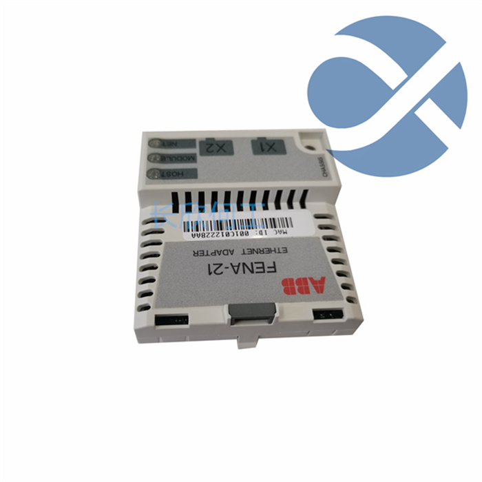
易卖工控网(www.ymgk.com)提供”FENA-21 Inverter Ethernet adapter module”,产品详情:品牌/厂家:ABB +8615359293870、型号:FENA-21+8615359293870、成色:全新、货期:现货 1天内发货、保修:180天,更多产品详情就上易卖工控网。
After completing all maintenance work on site and DCS, check and confirm whether the following conditions for re powering on are met
(1) Firstly, it is necessary to contact professionals such as process, electrical, equipment, and instrumentation to jointly confirm whether the power on conditions of the DCS system are met.
(2) After confirming that the main power supply provided by the electrical system meets the requirements, close the power supply main circuit breaker and check the output voltage separately.
(3) Close each branch circuit breaker inside the distribution box and check the output voltage separately.
(4) If equipped with UPS or regulated power supply, check if the output voltage of UPS or regulated power supply is normal.
System power on and testing
(1) Start the engineer station, server station, and operation station, and simultaneously power on each power box of the system for inspection.
(2) Check if each power box is working properly, if the power fan is working, and if the 5V and 24V indicator lights are working properly.
(3) Check if the system software and application software folders and files of each computer are correct; There is no significant change in the remaining space on the hard drive and it has passed the disk surface test.
(4) Compile and download the modified configuration.
(5) Observe the presence of faults from the real-time monitoring fault diagnosis of each operating station.
(6) Open the control station cabinet door and observe if the card is working properly and if there is a fault display (FAIL light on).
(7) Power supply redundancy test
Open one redundant AC~220VAC main incoming line separately, and the other AC power supply circuits lose power, but the system should still be able to work normally.
Turn on one redundant DC power source separately, turn off other DC power sources, and measure the voltage of 5V and 24V on the power terminals of each cage (rack) motherboard.
(8) Communication redundancy test: Connect one of the communication lines of each redundant communication line separately (disconnect the other communication lines), and use the download configuration function to test whether it is normal. If everything is normal, it indicates that the communication network is normal.
(9) Card redundancy test: Check whether the redundancy is normal by plugging and unplugging redundant cards that are mutually redundant.
Attention: If one of the redundant main control cards or data transfer cards is removed and inserted back, the other redundant card can only be removed after the data copy is completed, otherwise serious consequences will be caused during the production process.
Control and process parameter inspection
(1) Proofread the control and process parameters that have already been successfully run (due to configuration modifications and downloads, some parameters may have confusion and need to be inputted again).
(2) The parameters of replaced control circuits and newly added control circuits (programs) for on-site instruments (transmitters, regulating valves, etc.) need to be readjusted and debugged.
Contact information: 15359213550
Contact person: He Gong
Email: geabbdcs@gmail.com 386353502@qq.com
Official website: https://www.gyamazon.com , http://www.geabb.com

How to check for hardware malfunctions?
Hardware failures often manifest in the following aspects
The plug-in board of the module is not tightly connected to the bus base plate;
The dial switch is incorrect; The direction of the communication line wiring is incorrect;
Terminal matcher not connected;
The hardware jumper does not match the type required for the actual signal;
The system power supply inside the cabinet and the on-site power supply output are incorrect;
The hardware itself is faulty.
The results of the above issues are as follows:
Hardware board pole failure after power on (incorrect indicator light display status);
Equipment not working;
The system is working but the displayed corresponding measurement point values are incorrect, the system's output cannot drive on-site equipment, and so on.
How to handle software errors?
Problems arising from software configuration and hardware coordination errors
The database point configuration does not match the on-site signal connected to the corresponding channel;
Adding a mouse driver program to COM1 port causes the system to be unable to operate with the mouse while running online;
The printer does not print, etc.


