


 在线咨询
在线咨询


¥ 2043.00
¥ 2043.00
¥ 2043.00

¥ 2089.00

¥ 2089.00
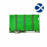
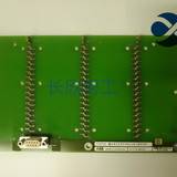
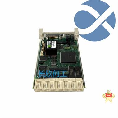
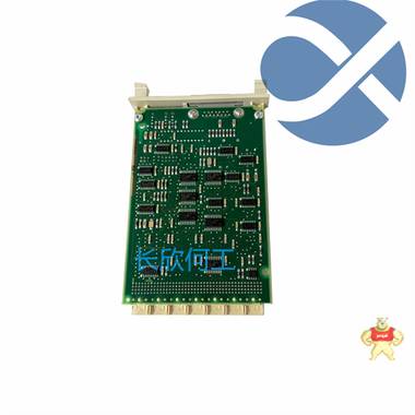
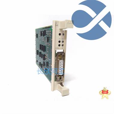
易卖工控网(www.ymgk.com)提供”CI546 3BSE012545R1 Embedded card supply”,产品详情:品牌/厂家:ABB +8615359293870、型号:CI546 3BSE012545R1+8615359293870、成色:全新、货期:现货 1天内发货、保修:180天,更多产品详情就上易卖工控网。
Product Overview:
The freely configurable safety module has 20 safety inputs and 4 safety outputs, 4 signals, 2 clocks, and 2 grounding switch outputs. It can be diagnosed through the bus gateway and meets SIL 3, Cat Category 4/PL e, SIL 3 safety level, EN 50156, pluggable straight in terminal block
Product specifications:
Product type: Safety equipment
Number of available expansion modules: 1 (high continuous current through PSR-TBUS: 4 A)
Overvoltage category: III
Pollution level: 2
Response time: 30 ms (plus the response time of PSR-TS-SDOR4)
Recovery time:<10 s
High power consumption under rated conditions: 6372mW (at a=20, b=2, c=4, e=2, Iclock=100mA, Isignal=100mA, IOut/GND=2A, IOut/Out=2A)
Rated operating mode: 100% meets the conditions
Interface: USB
TBUS DIN rail for expansion modules and bus couplers
Rated control circuit power supply voltage US: 18 V DC 30 V DC (including all tolerances, including residual voltage)
Rated control circuit power supply voltage US: 24 V DC (A1/A2)
Rated control power supply current IS: typical value 110 mA
Limiting continuous current: up to 6 A (for loop current paths A1/A1 and A2/A2)
Delay time: typical value of 20 ms (depending on load, in case of voltage drop of US)
Protection circuit: Yes, within the operating voltage limit range
Status display: 3x green LED, 1x red LED
Input Description: Number, HTL type
Input quantity: 10 (dual channel, up to SIL 3)
20 (single channel, up to SIL 2)
Input voltage range, "0" signal: 0 V DC 5 V DC (for safe shutdown)
Input voltage range, "1" signal: 11 V DC 30 V DC
Cable length: up to 2000 meters
Status display: 20 x green LED (1 LED per input)
Electricity consumption: typical value 4 mA
Output quantity: 4 (safe semiconductor output, up to Cat. 4 (according to EN ISO 13849-1 requirements))
2 (Negative Switching Output)
Precautions for protecting the circuit: Yes, within the operating voltage limit range
Short circuit protection: Yes
Output voltage:<5 V (low state)
Leakage current: up to 2 mA
Large capacitive load: 1 µ F (for electronic components)
Limit continuous current: 2 A (per channel, see reduced capacity)
2 A (total current of all outputs)
Rated output voltage: 24 V DC (powered by 24 V/0 V)
Rated output voltage range: 18 V DC 30 V DC (including all tolerances, including residual voltage)
Status display: 4 x green LED (1 LED per output)
Test pulse:<1 ms
Voltage: 24 V DC (powered by 24 V/0 V)
Limit continuous current: 100 mA
Test pulse:<1 ms
Pluggable: Yes
Connection method: straight in connection
Cross section of hard wire: 0.2 mm ² ... 1.5 mm ²
Cross section of flexible conductor with cold pressed head without insulating sleeve: 0.25 mm ² ... 1.5 mm ² (Only CRIMPFOX 6 wire clamps can be used)
Wire cross-section AWG: 24 sixteen
Width: 67.5 mm
Height: 112 mm
Depth 114.5 mm
Shell material: non reinforced polyamide PA
Shell color: yellow
Protection level: IP20
Insertion position low protection level: IP54
Environmental temperature (operating): -20 ° C 55 ° C
Environmental temperature (storage/transportation): -20 ° C 70 ° C
High altitude: up to 2000 meters (please refer to Appendix "Using PSR-TRISAFE modules at altitudes above 2000 meters")
Maximum allowable humidity (storage/transportation): 75% (average, sometimes 85%)
Permissible high relative humidity (operation): 75% (average, sometimes 85%)
Impact force (running): 10g( Δ T=11 ms, three impacts in each direction)
Contact information: 15359213550
Contact person: He Gong
Email: geabbdcs@gmail.com 386353502@qq.com
Official website: https://www.gyamazon.com , http://www.geabb.com

The deceleration time is a parameter that determines the time required for the frequency converter to slow down the motor. A longer deceleration time means that the time required for the speed to decrease to a complete stop of the motor is longer. Although many installers know to optimize acceleration time to prevent overcurrent issues during startup, deceleration time is often overlooked.
Adjusting the deceleration time is important for preventing overvoltage faults. When the motor loses power and continues to rotate due to the inertia of the load, overvoltage faults may occur. This rotation will generate electricity from the motor and feed it back to the frequency converter, causing the frequency converter to malfunction. In this case, an appropriate deceleration time will reduce the electricity generated by the deceleration load and prevent faults from occurring.
For example, if the user has a motor that controls the fan and needs 10 seconds to slow down and stop the fan, the frequency converter should be programmed using this deceleration time to extend the lifespan of the motor. However, please note that if a quick stop is required due to process or safety reasons, additional hardware may be required and relevant experts should be consulted.


闽公网安备 35020302034948号


 收藏商品
收藏商品

 当前商品暂无此评价~


 2778087246
 18150367963


 记住账号
记住账号

 QQ咨询
QQ咨询