


¥ 价格面议
¥ 价格面议
¥ 价格面议

¥ 价格面议
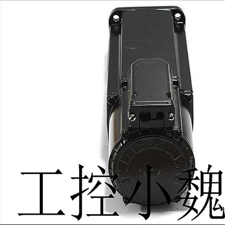
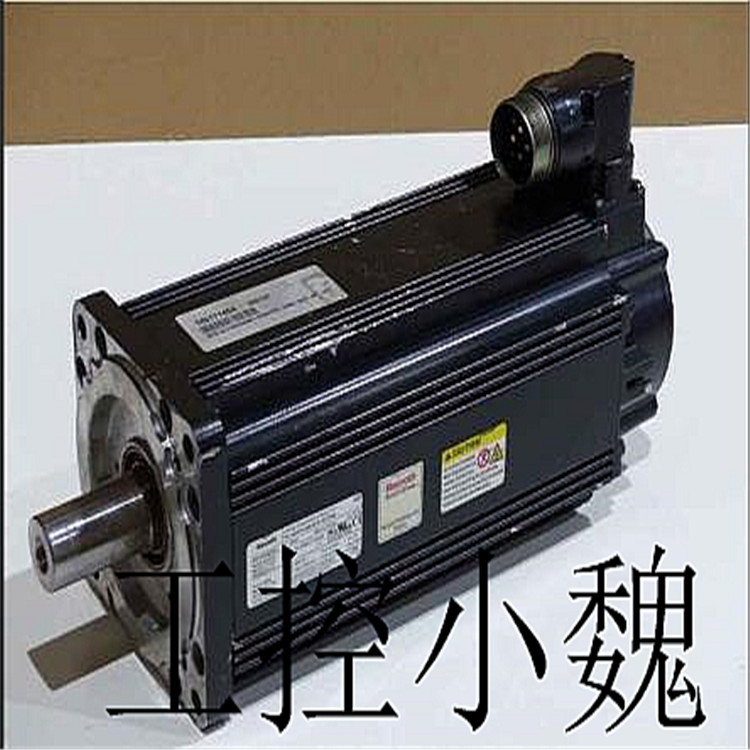
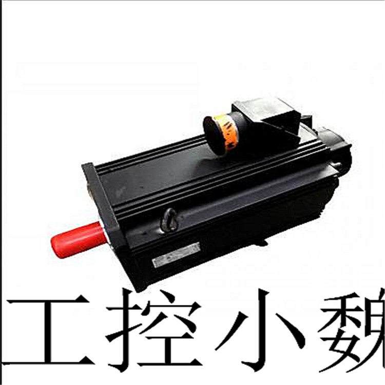
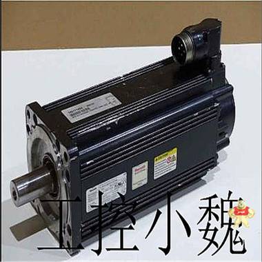
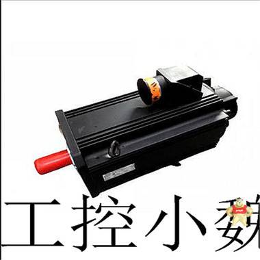
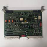
易卖工控网(www.ymgk.com)提供”MKD112B-024-GG0-LN伺服电机”,产品详情:品牌/厂家:Rexroth、型号:MKD112B-024-GG0-LN、成色:全新、货期:现货 1天内发货、保修:180天,更多产品详情就上易卖工控网。
MKD112B-024-GG0-LN分别为“运行时间显示”、“运行时间调整”、“暂停时间显示”和“暂停时间调整”,对象类型为数值型。(3)在“动画组态水泵控制”窗口中删除与定时器相关的图符,并且制作6个新的文字标签。
(4)制作如图的动画窗口。在设备窗口中添加一个“通用串口父设备”再添加一个“西门子_S7200PPI”。(5)选择好后就对设备进行属性设置,以便与MCGS进行通信。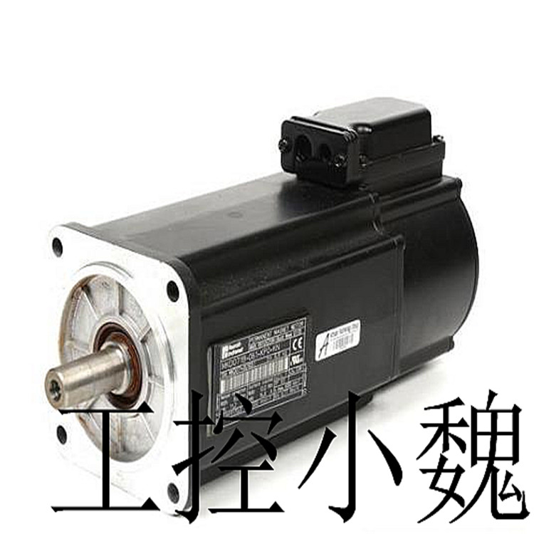

(6)在通用串口属性设置”串口端子号为“COM1”数据校验方式为“偶校验”采集数据为“同步采集”。0小采集周期设为200ms.【依据所接PLC型号进行设定】
(7)设置西门子PPI属性,添加4个i寄存器、2个Q寄存器、3个M寄存器和4个VW寄存器。
(8)在图纸上先画出PLC程序,注意为了较为正确的控制组态,所以在程序设计过程中要进行数据转换。加入转移指令和整数除法指令,将计时器时间除以10放到寄存器中。还要添加“上位机启动”和“上位机停止”。
(9)在联机监控操作时,打开MCGS时需要关闭Step7软件,然后进行通连道接,直到显示为0是就表示连接成功了,便可进行监控测试。
任务三机械手控制系统
机械手的运行控制较前两个任务还是增加了难度,
(1)首先我们先建一个工程将其命名为“机械手运行控制”再在用户窗口中新建一个窗口将其命名为“机械手控制”
(2)在用户窗口中建立所需的图符,
A.创建4个按钮,分别命名为启动、复位、定时器启动、定时器复位。
B.再用标签建立2个文本框分别命名为,计时时间、和时间到,和4个矩形框。
C.用矩形框建立机械手底座和用管道建立机械手横臂和竖臂,再用3个矩形建立抓手。
D.添加6个相同的步指示灯和2个启动和复位指示灯。其中6个步是下移、加紧、上移、左移、右移、放松。
E.关于要搬运的物块,当然自己要动手画出。用一个矩形和两个椭圆通过改变填充颜色和合成图符组成一个整体。
(3)在实时数据库里添加开关型数据分别为定时器启动、定时器复位、启动、复位、下移夹紧、上移、右移、放松和左移。左工件和右工件。
(4)再添加垂直移动量,水平移动量、计时时间和时间到等数据型数据。
(5)在各个图符里添加相关的属性,注意连接管子的两个矩形要合成图符因为要添加“水平移动量”属性。
(6)当相关属性在表达式里从实时策略里选完后,0后还要给机械臂添加大小变化的属性,其计算方法为臂伸长后的总长度=臂的实际长度+伸长的量,如何进行长度测量,先画一条直线打开查看栏里的状态条,便会在右下角显示长度,
(7)至于属性框里表达式的值则要通过下降的时间除以200ms
(8)在循环策略里添加脚本程序和定时器。
任务四 机械手运行监控
在任务二中已经介绍过监控的实际运用的意义,所以在此任务中就不再详细介绍。
(1)删除定时器策略及脚本程序策略。【在联机时,PLC完成控制任务,所以组态工程中的定时器和脚本程序就无用了】修改数据库中与定时器相关的4个数据对象,分别为“定时器启动”“定时器复位”计时时间和时间到,以提高运行环境效率。然后在添加4个新的数据对象,分别为“运行时间显示”、“运行时间调整”、“暂停时间显示”和“暂停时间调整”,对象类型为数值型。
(2)在“机械手运行控制”窗口中删除与定时器相关的图符,
(3)制作如图的动画窗口。
(4)在设备窗口中添加一个“通用串口父设备”再添加一个“西门子_S7200PPI”。
(5)选择好后就对设备进行属性设置,以便与MCGS进行通信。(6)在通用串口属性设置”串口端子号为“COM1”数据校验方式为“偶校验”采集数据为“同步采集”。0小采集周期设为200ms.【依据所接PLC型号进行设定】
(7)设置西门子PPI属性,在基本属性里添加4个i寄存器、14个Q寄存器、6个M寄,其中M2.0为上位机启动,M2.1为上位机停止。
(8)在图纸上先画出PLC程序,注意为了较为正确的控制组态,所以在程序设计过程中要进行数据转换。加入转移指令和整数除法指令,将计时器时间除以10放到寄存器中。还要添加“上位机启动”和“上位机停止”。
(9)在联机监控操作时,打开MCGS时需要关闭Step7软件,然后进行通连道接,直到显示为0是就表示连接成功了,便可进行监控测试。
任务五 分炼机械手监控系统
81001-450-53-r when writing this field, timer 4 loads the written value on the next rise, the edge of the timer clock, whether the timer is enabled or disabled. The value stored in this register will also be automatically reloaded (or timed out) when the terminal counts. When reading any field, the current count value is locked and returned. There are two modes that determine how to lock the count, depending on the "read latch select" bit in the WDT control status register (csr2). See csr2 for more information about these two modes, see the registration instructions. When reading this field, the current count value is locked and returned. There are two modes that determine how to lock the count, depending on the "read latch select" bit in the WDT control status register (csr2). See csr2 for more information about these two modes, see the registration instructions. Timer 4 current count register (tmrccr4) the current count of timer 4 can be read through timer 4 current count register (tmrccr4), located at address offset 0x28 in bar2 81001-450-53-r A-B high voltage converter module
1. Central processing unit (CPU)
Central processing unit (CPU) is the control center of PLC. It receives and
Store the user program and data input from the programmer, check the status of power supply, memory, VO and alarm timer,
And it can diagnose the syntax errors in the user program: when the PLC is put into operation, it first receives the on-site inputs in the form of scanning
Enter the status and data of the device, store them in the IO image area respectively, and then read the user program one by one from the user program memory
Sequence, after command interpretation, send the result of logical or arithmetic operation into VO image area or data storage according to the provisions of the instruction
Inside. After all user programs are executed, the output status or output register of the 1/o image area is finally stored
The data of is transmitted to the corresponding output device, and the cycle runs until it stops running.
In order to further improve the reliability of PLC, in recent years, double CPUs have been used to form a redundant system for large PLC, or
Voting system with three CPUs. In this way, even if a CPU fails, the whole system can still operate normally.
2. Memory
The memory storing system software is called system program memory.
(1) Memory type commonly used by PLC.
1) RAM (Random Assess Memory)。 This is - a read / write memory (RAM) whose access speed
Du is the fastest, supported by Keng battery.
2) EPROM (Erasable Progranmable Read Only Memory)。 This is an erasable read-only storage
All contents in the memory remain unchanged when the power is off (the contents of the memory can be erased under continuous ultraviolet irradiation).
3) EPROM (Electrical Erasable Programmable Read Only Memory)。 This is an electrically erasable
Read only memory except. The stored content can be easily modified by using a programmer.
(2) Allocation of PLC storage space. Although the maximum addressing space of CPUs of various PLCs is different, the root
According to the working principle of PLC, its storage space generally includes the following three areas: system program storage area and system RAM storage
Area (including i/o image area, system software equipment, etc.), user program storage area.
1) System program storage area. The system program equivalent to the computer operating system is stored in the system program storage area,
Including monitoring program, management program, command interpretation program, function subroutine, system diagnosis subroutine, etc. By the manufacturer
It is solidified in EPROM, and users cannot access it directly. Together with the hardware, it determines the performance of the PLC.
2) System RAM storage area. System RAM storage area includes i/o image area and various soft devices, such as logic
Coil, data register, timer, counter, index register, accumulator and other memory. Configuration control technology is a kind of computer control technology. It uses a computer to monitor certain equipment to make it work according to the control requirements. The computer configuration monitoring system composed of configuration control technology is mainly composed of controlled object, sensor, i/o interface, computer and actuator.
This training is to complete the man-machine interface production and program design of the configuration monitoring system with the help of MCGS configuration software platform. MCGS (monitor and Control Generated System) configuration software is a configuration software system developed by Beijing Kunlun Tongshi Software Co., Ltd. based on the window platform, which is used to quickly construct and generate the upper computer monitoring system. Through the collection and processing of field data, it provides users with a development platform to solve practical engineering problems in many ways, such as animation display, alarm processing, process control, report output, etc.
Because it is a software developed by Chinese people, it is all Chinese, which is very suitable for us to use. In addition, it can provide nearly 100 kinds of drawing tools and basic symbols, quickly construct graphical interfaces, and also provide thousands of exquisite library components, progressive colors and other kinds
The animation method can quickly build exquisite animation, and it also supports temperature control curves, planning curves, real-time curves, historical curves, XY and other industrial control curves. In short, using MCGS software can quickly complete the development of a computer monitoring and control system with stable operation, mature function, small maintenance and professional level. Next, I will introduce the detailed process of using MCGS configuration software to complete the task, as well as the problems encountered and solutions.
Task 1 pump operation control
Open the MCGS general configuration software, and we will see five parts: main control window, device window, user window, real-time database and operation strategy.
First, we will build a new project, name it pump control system and save it.
Then open the user window to complete the establishment of relevant symbols. When the teacher is building the project, he first established a real-time database, because he has a clear understanding of the control attributes of symbols, so for beginners, drawing symbols first is the first choice.
(1) Create a new window 0 in the user window, rename it pump operation control, and create an animated title "pump control" with a label in the animation window
(2) Draw water pump
In the software, we have been provided with an "object original library" in which we can select the original we want, so next, add a "pump 30" icon and confirm it. The size of the icon can be adjusted to achieve a beautiful effect
(3) Add two "buttons" under the pump to change the names to "start" and "stop" respectively. You can also double-click to change the background color of the button.
(4) Because we want to show the state of stop and start, we add two more indicator lights. In order to show the state of start and stop more clearly, we can also transform an indicator light by ourselves. The transformation method is to use an indicator light provided by a library as the transformation object, first decompose the unit, and then drag the front icon away, Decompose the bottom icon, change its color, add a "visibility" attribute, fill in the expression with @ switching value, and then set the relevant attributes of the other indicator.
(5) In order to display the time, we add two more buttons, namely "timer start" and "timer reset", and add two labels, namely "timing time" and "time to".
(6) Add four input boxes to set their properties as numeric,
(7) Now let's add the relevant data in the real-time database. The water pump, start, reset, timer start and timer reset are all on-off values, and the "timing time" and "time to" are numerical types.
(8) After the real-time data is established, we can associate the related expressions of the symbols in the user window. Due to the time control, we need to add a timer and a script program in the operation strategy, set the time value to 35 seconds in the timer attribute, and write the control program with if-then statement in the script program. Remember to use exit to divide the steps. Before finally entering the running environment test, you should adjust the attributes of the cycle strategy and change the timing cycle time to 200s.
Task 2 water pump operation monitoring
In the early stage, it only used the "equipment independence" of MCGS system to preliminarily realize the simulation operation of the water pump control system with the help of timer and script strategy in the water pump control configuration project, which did not achieve the purpose of real-time monitoring, so it is necessary to monitor the setting next.
We know that the pump operation control is mainly controlled by PLC, while MCGS system, on the one hand, needs to collect relevant data from PLC, change the value of the corresponding variable in the real-time database, and then display it in the form of animation of graphic components in the screen, so as to achieve the purpose of monitoring operation; On the other hand, it is also necessary to write the pause and running time set in the configuration environment of the upper computer into the PLC to adjust the running time of the water pump, and to control the operation and stop of the water pump hardware system through the start and stop buttons of the upper computer.
Open the previous "task one" and save it as "pump operation monitoring" to improve the "task one" configuration engineering animation and attribute settings.
(1) Delete timer policy and script program policy. [when online, PLC completes the control task, so the configuration Engineering
Timers and script programs in are useless]
(2) Modify the four data objects related to timers in the database, namely "timer start", "timer reset" timing time and time to improve the efficiency of the operating environment. Then add four new data objects, namely "run time display", "run time adjustment", "pause time display" and "pause time adjustment", and the object type is numeric.
(3) Delete the symbols related to the timer in the "animation configuration water pump control" window, and make 6 new text labels.
(4) Make the animation window as shown in the figure.

 记住账号
记住账号


 收藏商品
收藏商品


 2778087246
 18150367963


