


¥ 1495.00
¥ 1495.00
¥ 1495.00
¥ 1495.00
¥ 1495.00
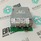
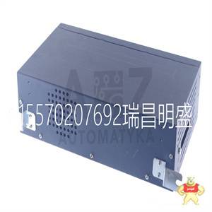
易卖工控网(www.ymgk.com)提供”10000-310-483786模块备件”,产品详情:品牌/厂家:0040-32460-504815、型号:10000-310-483786、成色:全新、货期:现货 1天内发货、保修:180天,更多产品详情就上易卖工控网。
10000-310-483786
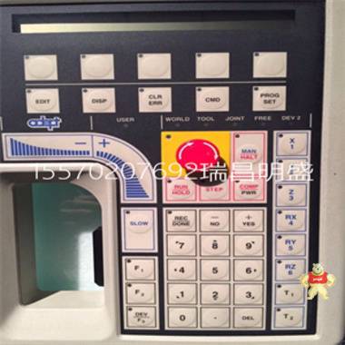
•测量读数;顶部显示的值
行和显示在底线上的单位标签。
•配置和校准提示。
按钮(两个)提供以下功能
配置和校准功能:
•零和量程设置,非交互式
自动将输出设置为4 mA或20 mA
使用“下一步”和“回车”按钮。
•4和20 mA点动设置,允许用户
容易地向上或向下增加mA输出信号
以精细的步骤匹配
外部仪表。
•线性或平方根输出
•用户输入的截止点为0%到20%
大流量。
•正向或反向输出
•阻尼调整
•启用/禁用可选外部零点
•温度传感器故障策略
•故障保护措施
•单位标签(显示底线)
•可设置的下限和上限值
传输和显示(顶行)
•重新设置范围
•输出百分比(%)
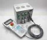
可选外部调零
外部按钮(图22)机构是
与电子设备室隔离
磁性激活内部簧片开关
穿过外壳。这消除了潜在的泄漏
湿气或污染物进入管道的路径
电子隔间。这种零位调整可以
被配置选择禁用。
图22带有板上按钮的LCD指示器
顶部工程
带盖子
远离的
可选
液晶显示器
指示器
“输入”
“下一步”按钮
按钮
下一个输入
可选
外部
零
按钮
Artisan Technology Group-质仪器…保证|(888)88-SOURCE | www.artistatg.com
PSS 2A-1C14 B
14页
操作、储存和运输条件
(a) 当使用传统结构代码78/79(高压侧和低压侧工艺盖中的pvdf插件)时,大超量程为2.1 MPa
(300 psi),温度极限为-7和+82°C(20和180°F);当使用DIN结构选项D2/D4/D6/D8时,
温度极限为0和60°C(32和140°F)。
(b) 选项J的选择将装有硅胶填充传感器的变送器的低温工作极限扩展至-50°C(-58°F)。
(c) 虽然LCD在“存储和运输限制”内的任何温度下都不会损坏,但更新速度会减慢,并且
在“正常工作条件”以外的温度下,可读性下降。
(d) 顶部覆盖,导管入口密封。
(e) 通过使用插入式短路棒,11.5 V dc可以减少到11 V dc;请参阅“电源电压要求”一节和图23。
(f) 传感器在垂直平面内处理浸湿的隔膜。
(g) 有关某些电气认证的环境温度限制,请参阅电气安全规范一节。
影响
参考
操作
条件
正常操作
条件(a)操作极限(a)
存储和
运输
限制
过程连接温度。
•使用硅胶填充液
•含氟惰性填充液
•24±2°C
(75±3°F)
•24±2°C
(75±3°F)
•-29至+82°C
(-20至+180°F)
•-29至+82°C
(-20至+180°F)
•-46和+121°C(b)
(-50和+250°F)
•-29和+121°C
(-20和+250°F)
•不适用
•不适用
电子设备温度
•带LCD指示器(c)
•24±2°C
(75±3°F)
•24±2°C
(75±3°F)
•-29至+82°C(g)
(-20至+180°F)(g)
•-20至+82°C(g)
(-4至+180°F)(g)
•-40和+85°C(g)
(-40和+185°F)(g)
•-29和+85°C(g)
(-20和+185°F)(g)
•-54和+85°C
(-65和+185°F)
•-54和+85°C
(-65和+185°F)
相对湿度(d)50±10%0至100%0和100%0及100%
非冷凝
电源电压–mA输出30±0.5 V dc 11.5至42 V dc(e)11.5和42 V dc(e)不适用
输出负载–mA输出650Ω 0至1450Ω 0和1450Ω 不适用
振动1米/秒2(0.1“g”)6.3毫米(0.25英寸)双振幅:
5至15 Hz,带铝制外壳和
5至9 Hz,316不锈钢外壳
- - - - - - - - - - - - - - - - - - - - - - - - - - - - - - -
0至30 m/s2(0至3“g”),从15至500 Hz
铝外壳;和
0至10 m/s2(0至1“g”),从9至500 Hz
316不锈钢外壳
11米/秒2
(1.1“g”)
从2.5到5 Hz
(装运中)
包装)
安装位置直立或
水平(f)
直立或水平
(f)
无限制不适用
Artisan Technology Group-质仪器…保证|(888)88-SOURCE | www.artistatg.com
PSS 2A-1C14 B
15页
性能规范
基于零的校准;钴镍铬或不锈钢传感器,含硅流体;在参考中
除非另有规定,否则为操作条件。URL=量程上限,Span=校准量程。
精度(线性输出)-表1(a)
(a) 精度包括线性、滞后和重复性。
(b) Span代码A增加±0.04%,Span增加±0.02%
代码E。
(c) 数字输出精度减去±0.01%。
精度(平方根输出)(a)
(a) 精度包括线性、滞后和重复性。
稳定性
每年的长期漂移小于URL的±0.05%
超过5年。
校准频率
校准频率为五年。五个
使用allowabl的值得出年份
10000-310-483786
10000-310-483786
• Measurement Readout; Value displayed on top
line, and units label displayed on bottom line.
• Configuration and Calibration prompts.
Pushbuttons (two) Provide the Following
Configuration and Calibration Functions:
• Zero and Span settings, non-interactive to
automatically set output to either 4 mA or 20 mA
using the “NEXT” and “ENTER” pushbuttons.
• 4 and 20 mA Jog Settings, allowing the user to
easily increment the mA output signal up or down
in fine steps to match a value shown on an
external meter.
• Linear or Square Root Output
• User-entered cutoff point from 0 to 20% of
maximum flow.
• Forward or Reverse Output
• Damping Adjustment
• Enable/Disable Optional External Zero
• Temperature Sensor Failure Strategy
• Failsafe Action
• Units Label (Bottom Line of Display)
• Settable Lower and Upper Range Values for
Transmission and Display (Top Line)
• Reranging
• Percent (%) Output
Optional External Zero Adjustment
An external pushbutton (Figure 22) mechanism is
isolated from electronics compartment and
magnetically activates an internal reed switch
through the housing. This eliminates a potential leak
path for moisture or contaminants to get into the
electronics compartment. This zero adjustment can
be disabled by a configuration selection.
Figure 22. LCD Indicator with On-Board Pushbuttons
TOPWORKS
WITH COVER
REMOVED
OPTIONAL
LCD
INDICATOR
"ENTER"
"NEXT" PUSHBUTTON
PUSHBUTTON
NEXT ENTER
OPTIONAL
EXTERNAL
ZERO
PUSHBUTTON
Artisan Technology Group - Quality Instrumentation ... Guaranteed | (888) 88-SOURCE | www.artisantg.com
PSS 2A-1C14 B
Page 14
OPERATING, STORAGE, AND TRANSPORTATION CONDITIONS
(a) When Traditional Structure Codes 78/79 (pvdf inserts in Hi- and Lo-side process covers) are used, maximum overrange is 2.1 MPa
(300 psi), and temperature limits are -7 and +82°C (20 and 180°F); when DIN Construction Options D2/D4/D6/D8 are used,
temperature limits are 0 and 60°C (32 and 140°F).
(b) Selection of Option -J extends the low temperature operative limit of transmitters with silicone filled sensors down to -50°C (-58°F).
(c) Although the LCD will not be damaged at any temperature within the “Storage and Transportation Limits”, updates will be slowed and
readability decreased at temperatures outside the “Normal Operating Conditions”.
(d) With topworks cover on and conduit entrances sealed.
(e) 11.5 V dc can be reduced to 11 V dc by using a plug-in shorting bar; see “Supply Voltage Requirements” section and Figure 23.
(f) Sensor process wetted diaphragms in a vertical plane.
(g) Refer to the Electrical Safety Specifications section for a restriction in ambient temperature limits with certain electrical certifications.
Influence
Reference
Operating
Conditions
Normal Operating
Conditions (a) Operative Limits (a)
Storage and
Transportation
Limits
Process Connection Temp.
• with Silicone Fill Fluid
• with Fluorinert Fill Fluid
• 24 ±2°C
(75 ±3°F)
• 24 ±2°C
(75 ±3°F)
• -29 to + 82°C
(-20 to +180°F)
• -29 to + 82°C
(-20 to +180°F)
• -46 and +121°C(b)
(-50 and +250°F)
• -29 and +121°C
(-20 and +250°F)
• Not Applicable
• Not Applicable
Electronics Temperature
• with LCD Indicator (c)
• 24 ±2°C
(75 ±3°F)
• 24 ±2°C
(75 ±3°F)
• -29 to + 82 °C(g)
(-20 to +180 °F)(g)
• -20 to + 82 °C(g)
(-4 to +180 °F)(g)
• -40 and +85°C(g)
(-40 and +185°F)(g)
• -29 and +85°C(g)
(-20 and +185°F)(g)
• -54 and +85°C
(-65 and +185°F)
• -54 and +85°C
(-65 and +185°F)
Relative Humidity (d) 50 ±10% 0 to 100% 0 and 100% 0 and 100%
Noncondensing
Supply Voltage – mA Output 30 ±0.5 V dc 11.5 to 42 V dc (e) 11.5 and 42 V dc (e) Not Applicable
Output Load – mA Output 650 Ω 0 to 1450 Ω 0 and 1450 Ω Not Applicable
Vibration 1 m/s2 (0.1 “g”) 6.3 mm (0.25 in) Double Amplitude:
from 5 to 15 Hz with Aluminum Housing and
from 5 to 9 Hz with 316 ss Housing
- - - - - - - - - - - - - - - - - - - - - - - - - - - - - - -
0 to 30 m/s2 (0 to 3 “g”) from 15 to 500 Hz with
Aluminum Housing; and
0 to 10 m/s2 (0 to 1 “g”) from 9 to 500 Hz with
316 ss Housing
11 m/s2
(1.1 “g”)
from 2.5 to 5 Hz
(in Shipping
Package)
Mounting Position Upright or
Horizontal (f)
Upright or Horizontal
(f)
No Limit Not Applicable
Artisan Technology Group - Quality Instrumentation ... Guaranteed | (888) 88-SOURCE | www.artisantg.com
PSS 2A-1C14 B
Page 15
PERFORMANCE SPECIFICATIONS
Zero-Based Calibrations; Cobalt-Nickel-Chromium or Stainless Steel Sensor w/Silicone Fluid; Under Reference
Operating Conditions unless otherwise Specified. URL = Upper Range Limit and Span = Calibrated Span.
Accuracy (Linear Output) - Table 1 (a)
(a) Accuracy includes Linearity, Hysteresis, and Repeatability.
(b) Add ±0.04% for Span Code A, and ±0.02% for Span
Code E.
(c) Subtract ±0.01% for digital output accuracy.
Accuracy (Square Root Output) (a)
(a) Accuracy includes Linearity, Hysteresis, and Repeatability.
Stability
Long term drift is less than ±0.05% of URL per year
over a 5-year period.
Calibration Frequency
The calibration frequency is five years. The five
years is derived using the values of allowable error
(% span), TPE (% span), performance margin
(% span), and stability (% span/month); where:
Power-up Time
Less than 5 seconds for output to reach first valid
measurement.
RFI Effect
The output error is less than 0.1% of span for radio
frequencies in the range of 27 to 1000 MHz and field
intensity of 30 V/m when the transmitter is properly
installed with shielded conduit and grounding, and
housing covers are in place. (Per IEC Std. 61000-4-3.)
Supply Voltage Effect
Output changes less than 0.005% of span for each
1 V change within the specified supply voltage
requirements. See Figure 19.
Vibration Effect
Total effect is ±0.2% of URL per “g” for vibrations in
the frequency range of 5 to 500 Hz; with double
amplitudes of 6.3 mm (0.25 in) in the range of 5 to
15 Hz, or accelerations of 3 “g” in the range of 15 to
500 Hz, whichever is smaller, for transmitter with
aluminum housing; and with double amplitudes of
6.3 mm (0.25 in) in the range of 5 to 9 Hz, or
accelerations of 1 “g” in the range of 9 to 500 Hz,
whichever is smaller, for transmitter with 316 ss
housing.
Position Effect
Any zero effect caused by mounting position can be
eliminated by rezeroing. There is no span effect.
Static Pressure Effect
The zero and span shift for a 7 MPa, 1000 psi,
change in static pressure is:
ZERO SHIFT (a)
SPAN SHIFT
±0.15% of Reading.
Switching and Indirect Lightning Transients
The transmitter can withstand a transient surge up to
2000 V common mode or 1000 V normal mode
without permanent damage. The output shift is less
than 1.0%. (Per ANSI/IEEE C62.41-1980 and
IEC Std. 61000-4-5.)
Ambient Temperature Effect
Total effect for a 28°C (50°F) change within Normal
Operating Condition limits is:
NOTE
For additional ambient temperature effect
when pressure s
UNIQUE PROCESS COVER AND CELL BODY
DESIGN
Biplanar Construction (Figure 2) maintains the
traditional horizontal process connections and vertical
mounting by providing a cell body contained between
two process covers, while still achieving light weight,
small size, and high standard static pressure rating of
25 MPa (3625 psi). This provides easy retrofit of any
conventional differential pressure transmitter, and
also is easily mounted in the horizontal position with
vertical process connections, when required.
Figure 2. Biplanar Construction Shown with
Traditional Horizontal Process Connections
Process Covers (Figure 2) are fully supported by the
cell body over their entire height. This prevents
bending and results in a highly reliable seal. Also, this
provides dimensional stability to the process covers,
ensuring that they will always mate properly with 3-
valve bypass manifolds.
Process Cover Bolts (Figure 2) are enclosed to
minimize corrosion and to minimize early elongation
with rapid temperature increases. The design makes
it less likely for the transmitter to release process
liquid during a fire.
Process Cover Gaskets are ptfe as standard; ptfe
provides nearly universal corrosion resistance, and
eliminates the need to select and stock various
elastomers to assure process compatibility.
Light Weight provides ease of handling, installation,
and direct mounting without requiring costly pipe
stands.
TRANSMITTER STRUCTURES
Traditional and low profile structures (LP1 and LP2)
are offered to accommodate and to provide flexibility
in transmitter installations. See paragraphs below.
Traditional Structure
The traditional structure (Figure 3) utilizes the right
angle design common to most DP transmitters in use
throughout the world. Process connections are
oriented 90 degrees from the transmitter centerline.
This traditional structure makes it easy to retrofit any
transmitters of similar design.
Sensor cavity venting and draining is provided for
both vertical and horizontal transmitter installation,
using innovative tangential connections to the sensor
cavity (Figures 4 and 5). Optional side vents are
offered for sensor cavity venting in the upright
position (Figure 6).
An extensive variety of process-wetted materials are
available for the process covers on this highly
versatile and widely used transmitter.
Figure 3. Vertical Mounting Showing
Process Connections at 90 degrees
Figure 4. Vertical Mounting - Cavity Draining
Figure 5. Horizontal Mounting -
Cavity Venting, and Self-Draining into Process Line
Figure 6. Vertical Mounting - Cavity Venting,
and Self-Draining into Process Line
CELL BODY
ENCLOSED
BOLTS
SUPPORTED
PROCESS
COVER
TRADITIONAL
STRUCTURE
PROCESS
CONNECTIONS
90˚
TRADITIONAL
STRUCTURE
PROCESS
COVER DRAIN SCREW
TRADITIONAL
STRUCTURE
TRADITIONAL VENT SCREW STRUCTURE
OPTIONAL
SIDE VENT
SHOWN
PLUG
TRADITIONAL
STRUCTURE
Artisan Technology Group - Quality Instrumentation ... Guaranteed | (888) 88-SOURCE | www.artisantg.com
PSS 2A-1C14 B
Page 5
Low Profile Structures
The low profile structures utilize an in-line design,
placing the process connections in line with the
transmitter centerline (Figures 7 and 8). This allows
mounting of the transmitter in the upright position with
the process connections facing downward, for
connection to vertical process piping or for mounting
directly to a three- or five-valve manifold.
The low profile structures provide a mounting style
similar to that used by competitive Coplanar™
transmitters. This makes it easy to select Foxboro
transmitters for both retrofit and new applications
where this type of installation is desired.
Transmitters with the low profile structure can be
attached directly to existing, installed Coplanar
manifolds, such as the Rosemount Model 305RC or
Anderson Greenwood Models MB3, MB5G, and
MB5P, by use of an optional adapter plate (Figure 9).
Also, when assembled to the same process piping or
manifold as a Coplanar transmitter, one of the
electrical conduit connections is located within ± one
inch of the similar conduit connection on the
competitive transmitter, assuring ease of retrofit or
conformance with installation design drawings.
All parts making up the low profile versions are
identical to the parts in the traditional version except
for the process covers and the external shape of the
sensor cell body.
For user convenience, two types of low profile
structures are offered, type LP1 and LP2. The
process covers are the only transmitter parts that
differ between structure types LP1 and LP2.
Refer to the sections that follow for further
descriptions of low profile structures LP1 and LP2


闽公网安备 35020302034948号


 收藏商品
收藏商品

 QQ咨询
QQ咨询
 当前商品暂无此评价~


 2778087246
 18150367963


 记住账号
记住账号
