


¥ 1495.00
¥ 1495.00
¥ 1495.00
¥ 1495.00
¥ 1495.00
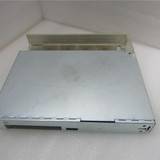
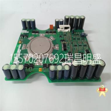
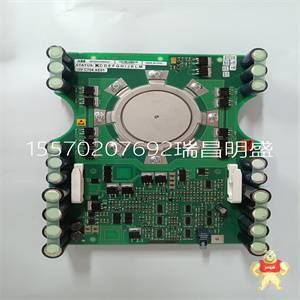
易卖工控网(www.ymgk.com)提供”5SXE05-0152模块现货”,产品详情:品牌/厂家:0040-32460-504815、型号:5SXE05-0152、成色:全新、货期:现货 1天内发货、保修:180天,更多产品详情就上易卖工控网。
5SHX1445H0001 2000年11月15日
|
November 15, 2000 Document Control Desk United States Nuclear Regulatory Commission Washington, DC 20555 Subject: Nuclear 1E Qualification of the TRICON TMR Programmable Logic Controller (PLC) - Revised Project Proprietary Documents Reference: 1. Letter, T. Martel (Triconex) to NRC, September 29, 2000, subject; Nuclear Qualification of the TRICON TMR PLC - Additional Project Qualification Document Submittals 2. Project Number 709 Gentlemen: In the referenced letter, Triconex submitted 3 proprietary documents for the NRC's review in connection with our TRICON lE Qualification Project, as listed below. These documents were accompanied by a request for withholding from public disclosure per 1OCFR2.790 and the required affidavit. 1. Reliability/Availability Study 7286-531 Rev 0 2. Certificate of Conformance 7286-542 Rev 0 3. Master Configuration List 7286-540 Rev 22 Non-proprietary versions of these documents were not provided at the time. Also, the proprietary portions of these documents were not specifically identified as requested by the staff. To resolve these documentation concerns, we are enclosing revised copies of the documents listed above, marked up as requested to show areas of proprietary information (please note that content has not changed). Also provided are non-proprietary versions of these documents for the public record with proprietary areas deleted. These enclosed documents replace and supersede earlier versions provided. As indicated in the September 29, 2000 letter, the enclosed documents are considered proprietary where so marked and should be withheld from public disclosure per 1OCFR2.790. The affidavit provided in the September 29, 2000 letter still applies to these documents. invensys An Invensys company NRC Document Control Desk, November 15, 2000 If you have any questions regarding the enclosed documents, please contact me at (281) 360-6401 or Mr. Michael Phillips at (949) 699-2111. Sincerely, J. Troy Mtel, P. E. Triconex Nuclear Qualification Project Director Enclosures cc: L. Raynard Wharton, NRC (w/o attachments) P. Loeser, NRC (w/o attachments) Page 2 TRICONEX DOCUMENTS NON-PROPRIETARY VERSIONS 1. Reliability/Availability Study 2. Certificate of Conformance 3. Master Configuration List 7286-531 7286-542 7286-540 Rev 0 Rev 0 Rev 22 ---------------------------------------------------------- "TRI CONEX Project: NUCLEAR QUALIFICATION OF TRICON PLC SYSTEM Purchase Order No.: ST - 401734 Project Sales Order: 7286 RELIABILITY/AVAILABILITY STUDY FOR TRICON PLC CONTROLLER Document No.: 7286-531 Revision 0 January 14, 2000 NON-PROPRIETARY MARKUP VERSION - Areas of proprietary information blanked. - Adjacent letter (a, b, c, d, c, f) corresponds to Triconex proprietary policy categories (ref. 7/17/00 letter to NRC, Affidavit, section 5). -T iRICONEX Iýocument: I7286-531 ITitle: IReliability/Availability Study for Tricon PLC Controller Revision: 0 Page: 2 of 3 [Date: 01/14/00 Document Change History Revision Date Change Author 0 01/14/00 Initial issue. Craig Swanner MTRICOWEX IDocument: 1 7286-531 I Title: I Reliability/Availability Study for Tricon PLC Controller Revision: 0 Page: 3 of 3 IDate: 101/14/00 SEE ATTACHED MPR ASSOCIATES CALCULATION No. 426-001-CBS-01, Revision 1 Pages: 1 through 27 A- I through A-2 B- I through B-7 C- I through C-5 MPR Associates, Inc. I M PR 320 King Street Alexandria, VA 22314 CALCULATION TITLE PAGE Client Triconex Corporation Page 1 of 27 + Appendices Project Tricon PLC Qualification Task No. 426-9901-001-0 Title Calculation No. Reliability Study for Tricon PLC Controller 426-001 -CBS-01 Preparer/Date Checker/Date Reviewer/Approver Date Rev. No. 16- 12- 1 ?/ ? 1 /,0loo QUALITY ASSURANCE DOCUMENT This document has been prepared, checked, and reviewed in accordance with the Quality Assurance requirements of 1 OCFR50 Appendix B, as specified in the MPR Quality Assurance Manual. MPR Associates, Inc. WMPR 320 King Street Alexandria, VA 22314 RECORD OF REVISIONS Calculation No. Pr ared By CheckeBy 426-001-CBS-01 4 n yPage 2 Revision Description 0 Initial Issue 1 Revised to address minor comments from Triconex. Revisions are indicated by a bar in the right margin. Only page 25 is affected. MPR Associates, Inc. I M PR 320 King Street Alexandria, VA 22314 Calculation No. pared By 426-001-CBS-01 Page 1. PURPOSE The purpose of this calculation is to document a reliability/availability study of the Tricon PLC controller for use in nuclear safety-related applications. The reliability study is performed to meet the requirements of Section 4.2.3 of Reference 1. 2. RESULTS A Tricon TMR PLC using a combination of modules specified in Reference 1 is analyzed for reliability and availability using a Markov model of the system. For a one year periodic test interval, the mean time to failure due to a spurious trip (MTTF) is 231.4 years resulting in an overall availability of 99.9988%. For the same test interval, the average probability of failure on demand (PFDavg) is 4.686 x 10⁻⁵ resulting in a safety availability of 99.9953%. Detailed results for different periodic test intervals are presented in Tables 4-2 and 4-3. Both the overall and the safety availabilities determined for the Tricon TMR PLC are greater than the recommended goal of 99% per Reference 1. Appendix C examines the reliability of the Tricon TMR PLC for a two week period in a post accident environment. In the post accident period, the overall availability is 99.7121%, and the safety availability is 99.9377%. As before, both of these results exceed the recommended goal of 99% stated in Reference 1. MPR Associates, Inc. WMPR 320 King Street Alexandria, VA 22314 Calculation No. Calcuatio No.Page Checked By L 426-001-CBS-01 3. APPROACH The Tricon TMR PLC is a programmable logic controller that can accept input signals, make appropriate decisions with a main processor, and send output signals. The input and output signals can be analog or discrete digital. The PLC is modular, meaning that each of the functions are performed by various types of cards which are plugged into the main chassis of the system. Consequently, one Tricon TMR PLC can have any number of configurations. Each module of the Tricon TMR PLC has at least 3z2-0 redundancy meaning that one channel can be lost and the module still functions properly. The Tricon TMR PLC can be used to replace analog reactor protection or engineered safety features actuation systems in nuclear power plants. The input modules can accept input from current plant wiring, the main processor would replace the current analog and discrete logic circuits, and -the output modules can generate signals comparable to the current relays. Because these systems are critical to the safe operation of the reactor, the replacement digital PLC must have a high degree of reliability and availability. EPRI TR-107330 (Reference 1) has been written to specify generic requirements for qualifying PLCs for safety-related applications in nuclear plants. This calculation addresses the requirements specified in Section 4.2.3 of Reference 1 regarding the reliability and availability requirements for PLCs. For all nuclear plant applications, one Tricon TMR PLC is used for each channel of a safety system. Losing two redundant legs inside the triple redundant Tricon does not necessarily lead to a system failure. Therefore, the reliability evaluations performed in this calculation assuming the Tricon TMR PLC only has 3-2-0 redundancy are very conservative for the actual applications in nuclear plant safety systems. It should also be noted that this calculation does not address software common cause failures. 3.1 System Configuration Analyzed Per Section 4.2.3.2 of Reference 1, the system in the following table is representative of the full range of components of the PLC. The Tricon TMR PLC module used to comply with the EPRI guidelines is also shown in the table. For cases where more than one type of Tricon module meets the EPRI component type, the Tricon module with the highest failure rate is chosen for evaluation. WM-PRMPR Associates, Inc. 320 King Street Alexandria, VA 22314 Calculation No. 426-001-CBS-01 Table 3-1. Tricon Modules EPRI Section Component Type Range of Tricon Modules 4.2.3.2.A 3 Discrete Input Modules 3501E, 3502E, 3503E, 3504E, 3505E, 3510 (pulse input) 4.2.3.2.B 2 Analog Input Modules 3700A, 3701, 3703E, 3704E, 3706A 3708E 4.2.3.2.C 1 Analog Output Module 3805E 4.2.3.2.D 3 Discrete Output Modules 3601E, 3603E, 3604E, 3607E, 3611E, 3623, 3624 1 Relay Output Module Not included in Tricon TMR for safety applications 4.2.3.2.E 1 High-level Language Module Included in main processor 4.2.3.2.F Support Module (Note 1) 4.2.3.2.G Ancillary Devices Not required for Tricon TMR 4.2.3.2.H Main Processor (3 required) 3006 4.2.3.2.1 Power Supply 8310, 8311, 8312 4.2.3.2.J Chassis Included in power supply 4.2.3.2.K Interconnect Devices Not required for Tricon TMR 4.2.3.2.L Modules necessary for Not required for Tricon TMR redundancy 4.2.3.2.M Ringback signals Included in Input/Output Modules Notes: 1. Support modules are not necessary for normal operation of the Tricon TMR. A communication module is required to reconfigure the system. IMPR Associates, Inc. O M PR 320 King Street Alexandria, VA 22314 Calculation No. Byecked By Page 426-001-CBS-01 3.2 Markov Model or Safe Failures Both the availability and the safety availability can be determined from a Markov model of the Tricon TMR PLC in the configuration described above. A Markov model uses a state diagram of various failure states of the system. From this model, the probability to be in any one state at a given time can be predicted. Using the combined probabilities of various failed states the mean time to failure due to a spurious trip (MTTF) and the probability of failure on demand (PFD) can be calculated for the system. These quantities are directly related to the availability and the safety availability. Failures can be generally classified into two categories: safe and dangerous. Safe failures are failures that result in the safety system failing into a safe configuration. For example, most safety systems including the Tricon TMR are designed to actuate upon complete failure of both power supplies. Dangerous failures are failures that result in the system failing to perform its intended safety function. Each category of failure can be further classifed into detected and undetected failures. Detected failures can be repaired on-line. Undetected failures are only detected and repaired during off-line periodic testing. 3.2.1 Model Description for Safe Failures. The Markov model for a safe spurious trip is shown in Figure 3-1. Note that this figure is developed using the methodology described in Reference 5. The Tricon TMR is a fail safe PLC with triplicated inputs (3-2-0), triple redundant main processor with communication, and a quad output voter. As required by Reference 1, the Markov model includes the main processor, a digital input module, an analog input module, a digital output module, and an analog output module. Along with each input/output microprocessor, the Markov model includes each input/output circuit. Also included is the dual power supply. The first state in the Markov model is the system operating normally with no failures. The intermediate states are when one channel of the various modules fail. The last state is when a second failure causes the system to trip spuriously. The probability of moving from one state to another (i.e., probability of failure or repair) are shown by the arrows. Note that constant failure and repair rates are assumed. Also time steps are assumed to be short so that the probability function can be estimated as shown below: P(t) = 1 - e- = I t Each intermediate failure state is described below. All equations and transition coefficients are taken from the fail safe Markov model for a triplicated PLC with a quad output voter developed in Draft 12 of ISA SP.84.02 (see Reference 5). MPR Associates, Inc. WMPR 320 King Street Alexandria, VA 22314 Calculation No. PraredChecked By 426-001-CBS-01 States 2 and 3- Digita Input Each digital input model is triplicated with 3-2-0 capability. Each module consists of three triplicated legs. State 2 is the failure of one of the digital input microprocessor modules. State 3 is the failure of one of the digital input circuits to an input module. The transitions from the initial state to the intermediate states representing an initial failure of one of three input micro processors or input circuits are given by: kl,2 = 3 nd XsiPd kl,3 = 3 nd nicdn •si The transitions from the intermediate state to the initial state representing the repair of the initial failure are given by: k2,1 -" Aipd k3,1 = /Jicd The transitions from the intermediate state to a spurious trip representing a failure in one of the two remaining input channels or main processors are given by: k2,12 = 2 (X•smp +I + ni sid) k3,12 = 2 (mp + ipd + xSic) Where: t = Probability of transition from the ith to the jth state nd = Number of digital input modules nic = Number of inodt circuits for each digital input module Xp i = Safe failure rate for digital input microprocessor Xs • = Safe failure rate for digital input circuits ;S = Safe failure rate for main processor •A = Effective repair rate of digital input microprocessor Aid = Effective repair rate of digital input circuit MPR Associates, Inc. AMPR 320 King Street Alexandria, VA 22314 Calculation No. Pr ared By Checked By Page 426-001-CBS-01 /( States 4 and 5- Anal nýput Each analog input model is triplicated with 3-2-0 capability. Each module consists of three triplicated legs. State 4 is the failure of one of the analog input microprocessor modules. State 5 is the failure of one of the analog input circuits to an input module. The transitions from the initial state to the intermediate states representing an initial failure of one of three input micro processors or input circuits are given by: kl,4 = 3 na sipa kl,5 = 3 naniea X ica The transitions from the intermediate state to the initial state representing the repair of the initial failure are given by: k4,1 = Lipa k5,1 = Aic The transitions from the intermediate state to a spurious trip representing a failure in one of the two remaining input channels or main processors are given by: k4,2 = 2 (X•mp + XSipa + nica X•Sica) k 5,12 - 2 (XLsmp + Xsipa + xsim) Where: na = Number of analog input modules nica = Number of input circuits for each analog input module IS p = Safe failure rate for analog input microprocessor ,XS = Safe failure rate for analog input circuits ALipa = Effective repair rate of analog input microprocessor Aia = Effective repair rate of analog input circuit WIMPR MPR Associates, Inc. 320 King Street Alexandria, VA 22314 Calculation No. 426-001-CBS-01 States 6 and 7- Each digital output module has a triplicated output processor with a quad voter output circuit. State 6 is the failure of one of the inputs into the digital output microprocessor modules. State 7 is the failure of one of the digital output circuits. The transitions from the initial state to the intermediate states ate given by: kj,6 kl,7 3 md X•.pd 4 md nocd 1.sOd The transitions from the intermediate state to the initial state representing the repair of the initial failure are given by: k 6 ,1 k7, 1 /.Lood The transitions from the intermediate state to a spurious trip representing a failure in one of the two remaining input channels or main processors are given by: k6,12 = 2 (,Xsmp + X•Sp) + (5 / 3) noX ;sow k7, 12 = (5 / 4) (XSmp + XSopd) + '.So•d Where: md nocd XS ocd /-Lopd //Lood Number of digital output modules Number of output circuits for each digital output module Safe failure rate for digital output microprocessor Safe failure rate for digital output circuits Effective repair rate of digital output microprocessor Effective repair rate of digital output circuit SMPR MPR Associates, Inc. 320 King Street Alexandria, VA 22314 Calculation No. hcked By 426-001-CBS-01 U States 8 and 9-AnaloxOif• • Per Reference 8, each analog output module is triplicated for 3-2-1-0 capability meaning the triplicated input from the main processor requires three faults before a failure condition is reached. Since the probability of failure for the module is third order (_A3), its effect on the mean time to failure can be neglected. The transitions are: kl,8 = k1,9 = k8,12 k9,12 - 0 0 0 0 The transitions from the intermediate state to the initial state representing the repair of the initial failure is given by: k8,1 k9,1 o'opa PAoca Where: o'apa P'oca Effective repair rate of analog output microprocessor Effective repair rate of analog output circuit State 10- Main Processor There are triple redundant main processors. State 10 is the failure of one of the three main processors. The transition from the initial state to the intermediate state is given by: k1,0 = 3 .Smp The transition from the intermediate state to the initial state representing the repair of the initial failure is given by: ko, = A'mp The transition from the intermediate state to a spurious trip representing a failure of any one of the circuits in the other two channels is: k10,12 = 2(.Smp + ndA XSipd + nd nic XsicA + na XSipa + na nia )'Sica + md ASop- +md no.d ASod) MPR Associates, Inc. WMPR 320 King Street Alexandria, VA 22314 Calculation No. red By Checked By Page 1 426-001-CBS-01 Where: AZmp = Effective repair rate of main processor State 11- Power Supply State 11 is the failure of one of the dual power supplies in a channel. The transition from the initial state to the intermediate state is given by: k1,1 = 2 l X•s The transition from the intermediate state to the initial state representing the repair of the initial failure is given by: k11,1 = / The transition from the intermediate state to a spurious trip representing failure of the remaining power supply in the channel is given by: k11, 12 = s Where: 1 = Number of power supplies per channel XS = Safe failure rate for power supply M =ps Effective repair rate of power supply Effects of Common Cause Failures The effects of dual or triple mode failure is modeled directly as a transition from the initial state to the spurious trip state. The common cause failure includes two factors. The first factor (P3) is for the chance of the remaining two channels failing after the first channel fails. Three safe failures or three dangerous detected failures of any channel would cause a spurious trip. The second factor (P2) is for the chance of a second channel failing after the first fails. Two safe undetected failures could cause a spurious trip. Since no clear software model exists, the software contribution to common cause failure is not modeled or included. The common cause failure transition is given by: MPR Associates, Inc. F M PR 320 King Street Alexandria, VA 22314 Calculation No. / Prered By Checke~I By PreIL Page 12 426-001-CBS-01 k1, 3 P 3 [XPADUmp+ n (Xi ADU + - DU)+ _- "DU m X. - X + - ni nI + ) na (Aipa Di a ica ica n -i ica) md (-.pd - XDopd + no . -nod oDU o) + 3 P2 [-SUmp + nd (-SUipd + ni Xsui) + na (Aipa + ni • suipa) + md (XSUpd + nod .SUod)] + 2 P2 1 •.• Where: P2 - Fraction of single module or circuit failures that result in the failure of an additional module or circuit performing the same function as the original failure P3 = Fraction of single module or circuit failures that result in the failure of two additional modules or circuits performing the same function as the original failure m = Total failure rate of main processor XD5 = Dangerous undetected failure rate of main processor ASU mp Safe undetected failure rate of main processor A = Total failure rate of digital input microprocessor Xu Dangerous undetected failure rate of analog input microprocessor XSU ip Safe undetected failure rate of analog input microprocessor X = Total failure rate of digital input circuit .DU i=d Dangerous undetected failure rate of analog input circuit ).SU Safe undetected failure rate of analog input circuit XA = Total failure rate of analog input microprocessor TaI p Dangerous undetected failure rate of analog input microprocessor ASU aD Safe undetected failure rate of analog input microprocessor X.SSaf Total failure rate of analog input circuit mo_ 'DUi = Dangerous undetected failure rate of analog input circuit ASUica = Safe undetected failure rate of analog input circuit A = Total failure rate of digital output microprocessor ISU Dangerous undetected failure rate of digital output microprocessor Xsu opd Safe undetected failure rate of digital output microprocessor .o=d Total failure rate of digital output circuit xDUoc - Dangerous undetected failure rate of digital output circuit .SU = Safe undetected failure rate of digital output circuit X = Total failure rate of power supply *MPR MPR Associates, Inc. 320 King Street Alexandria, VA 22314 Calculation No. 426-001-CBS-01 3.2.2 Solution Tevkique for Safe Failure Markov Model. The effective repair rate includes the repair for detected and undetected safe failures. Detected safe failures can be repaired on-line at a much faster rate. Undetected safe failures can only be repaired after the system is taken off-line for periodic testing. The effective repair rate is determined below. The safe failure rate can be broken down as: iS = CSXSD + (1_ CS) 'sU Where: XSD iSU Cs Safe failure rate of a component Safe detected failure rate of a component Safe undetected failure rate of a component Fraction of safe failures detected by diagnostic coverage The generalized Markov model for safe failures is shown below: Where:r 0 /-ot A2pt Failure rate from the intermediate state to the spurious trip state Repair rate when detected due to on-line testing Repair rate for off-line periodic testing This model can be simplified to the following by determining the effective repair rate. Firste MPR Associates, Inc. I M P R 320 King Street Alexandria, VA 22314 Calculation No. Pre red By Checked By 426-001-CBS-01 Where: = Effective repair rate The effective repair rate can be determined by equating the MT'YF for each model. After algebraic manipulation, the MTTF's can be shown to be equal if: 1 / (, + 0) = Cs / (Lot + 0) + (1- CS) / (@,Lpt + 0) Solving for the effective repair rate yields: A, = [(1 - Cs) /Apt.+c + C0t+ AptA03 / [CSAP, + (1- CS) A, + 0] The MTTF can be determined from the Markov model by integrating the probability for the time that the system is in a non-failed states. States 1 through 11 are the non-failed states. Therefore, the MT1F
| |


闽公网安备 35020302034948号


 收藏商品
收藏商品

 QQ咨询
QQ咨询
 当前商品暂无此评价~


 2778087246
 18150367963


 记住账号
记住账号
