


¥ 1495.00
¥ 1495.00
¥ 1495.00
¥ 1495.00
¥ 1495.00
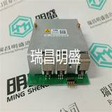
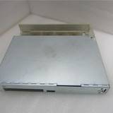
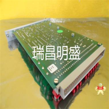
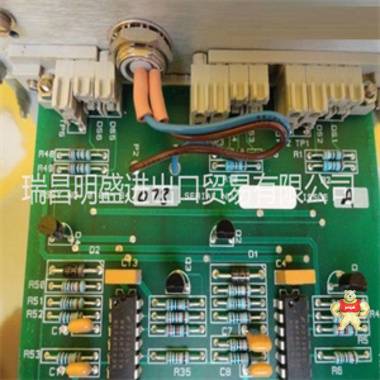
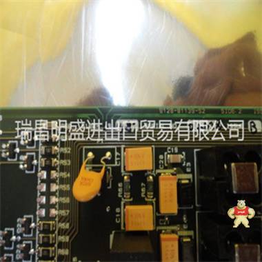
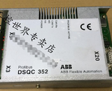
易卖工控网(www.ymgk.com)提供”150-002540-501525模块备件”,产品详情:品牌/厂家:0040-32460-504815、型号:150-002540-501525、成色:全新、货期:现货 1天内发货、保修:180天,更多产品详情就上易卖工控网。
Pall-504112
技术数据系统
开发了CS 31系统
根据国际标准IEC 1131-2。
● 操作条件
–温度:
● 操作0°C…+55°C 32。。。131华氏度
● 存储-40°C…+75°C-40。。。167°F
● 运输-25°C…+75°C-13。。。167°F
-湿度符合DIN 40040 F级,无
冷凝:
● 全年平均值≤ 75%
● 每年多30天95%
● 在其他日期
年份,有时为85%
–气压:
● 活动≥ 800百帕(≤ 2000米)
● 存储≥ 660百帕(≤ 3500米)
● 机械数据
–程度
防护IP 20
–外壳UL94 V0
UL94 V1适用于中央单元90级,
连接器07KPxx和装置ICDxx
–三者相互振动
垂直轴10 Hz。。。57赫兹
连续:0.0375 mm振幅
偶然:0.075 mm振幅
57赫兹。。。150赫兹
连续:0.5 g加速度
偶尔:1.0 g加速度
–冲击偶尔漂移至15 g,11 ms,
三个相互之间各有一个半正弦
垂直的轴
–对电源>30 VAC的装置的影响。
根据IEC 950:钢球承受
质量为500 g的试验应自由下落
从1300 mm的高度
● 安装
–DIN导轨35 mm
–螺钉安装螺钉Ø4 mm(M4)
● 串行接口
–对于RS485的连接,使用
中央单元至螺纹端子
远程装置
–用于编程和RS232-C
设置参数9极D连接器
(女性)
● 结束
–在插入式基座ECZ上,仅使用60°C铜导线
横截面:
–总线接线端子:双绞线
AWG 24(0.22 mm2
)至AWG 18(0.8 mm2
)
–接地端子:刚性或绞合连接器
AWG 10(5.2 mm2
)
–其他端子:
● 输入:绞合连接器
AWG 18(0.8 mm2
)至AWG 14(2.1 mm2
)
● 输出:绞合连接器
AWG 14(2.1 mm2
)
● 电源
AWG 14(2.1 mm2
)
–在可拆卸端子2.5 mm2(铜N°
AWG14)
块(小截面)
–可拆卸端子1.5 mm2(铜N°
AWG16)
块(小截面)
–拧紧7磅的螺钉。英寸(0.8牛米)
扭矩(仅供参考)
● 电源连接
–24 VDC(过程和24 VDC
电源(-20%,+25%,即19.2…30V)
包括波纹
纹波系数<5%
–120 VAC电源120 VAC
(-15%,+10%,即102…132V)
50 Hz或60 Hz(±5%)
–230 VAC电源230 VAC
(-15%,+10%,即195.5…253V)
50 Hz或60 Hz(±5%)
● 电压下降和中断
–直流电源中断时间≤ 10毫秒
两者之间的时间间隔
滴≥ 1秒
2一般特征1.1-2 ABB Procontic CS31/版本:04.96-FRCTL
–交流电源中断时间≤ 0.5周期
两者之间的时间间隔
滴≥ 1秒
● 爬电距离和电气间隙
根据EN 61131-2/
IEC1131-2
● 缘测试电压
缘测试电压
符合IEC 1131-2
● 电磁兼容性(EMC)
–静电放电(ESD)符合
IEC 1000-4-2
(严重级别3)
测试峰值电压:
● 通过空气放电时8 kV
● 出院时
通过继电器触点6 kV
两次放电之间的时间>1s
每次放电的次数
选定点10
–辐射电磁
现场抗扰度测试根据
IEC 1000-4-3
场强10伏/米
(严重级别3)
频率范围27 MHz至1000 MHz
扫描速度1.5 x 10E-3
十年/秒
–快速瞬变脉冲群测试(FTT),根据
IEC 1000-4-4
干扰电压:
电源端子115/230 V 2 kV
电源端子24 V 2 kV
输出端子24 V 1 kV
输出端子115/230 V 2 kV
输入端子24 V 1 kV
输入端子115/230 V 2 kV
模拟输入/输出端子1 kV
CS 31母线2 kV
编程接口0.5 kV
–浪涌抗扰度符合
IEC 1000-4-5
测试电压
非对称耦合共模
电源(115/230 VAC)2 kV
电源(24 VDC)1 kV
数字输入/输出1 kV
测试电压
对称耦合差模
电源(115/230 VAC)1 kV
电源(24 VDC)1 kV
数字输入/输出1 kV
● ABB Procontic CS 31系统总线
CS 31总线为屏蔽双绞线RS485
–交叉0.22。。。0.8 mm2
(编号:
AWG 24。。。编号°
AWG 18)
–扭转>10/m
–电阻≤ 100Ω/公里
–阻抗
特征100至150Ω
–电容<150 nF/km
–防护罩
–终止120Ω, 1/4瓦
电阻器连接在
公共汽车的尽头
–点数
共31个从节点+1个主节点
2 ABB Procontic CS31/版本:04.96-FRCTL 1.1-3一般特性
● 连接
应在整个过程中使用相同类型的电缆
安装系统总线(RS 485)。
避免总线中断,例如
编组柜处的连接电缆。
当对需要中断总线时,
它必须连接到端子的同一侧。
例子:
93 C 003 D 93 C 002 D
1.1.2 CS 31系统的安装
概述
必须遵守一些安装规则。这些规则
涉及
103F3505-30XE42-504989
Pall-504112
Technical data system The CS 31 system is developped according to the international standard IEC 1131-2. ● Operating conditions – Temperature : ● operation 0 °C ... + 55 °C 32 ... 131 °F ● storage - 40 °C ... + 75 °C - 40 ... 167 °F ● transport - 25 °C ... + 75 °C - 13 ... 167 °F – Humidity acc. to DIN 40040 class F without condensation : ● average over the year ≤ 75 % ● up to 30 days of a year 95 % ● on the other days withregard to the average of the year, occasionnally 85 % – Air pressure : ● operation ≥ 800 hPA (≤ 2000 m) ● storage ≥ 660 hPA (≤ 3500 m) ● Mechanical data – degree of protection IP 20 – housing UL94 V0 UL94 V1 for central units serie 90, coupler 07KPxx and units ICDxx – vibration each of three mutually perpendicular axes 10 Hz ...57 Hz continuous : 0.0375 mm amplitude occasional : 0.075 mm amplitude 57 Hz ... 150 Hz continuous : 0.5 g acceleration occasional : 1.0 g acceleration – shocks occasional excursion to 15 g, 11 ms, halfsine in each of three mutually perpendicular axes – impact for units with a power supply > 30 VAC. withstand According to IEC 950 : a steel sphere test with a mass of 500 g is to fall freely from a height of 1300 mm ● Mounting – DIN rail 35 mm – Screw mounting screws Ø 4 mm (M4) ● Serial interfaces – for connection of the RS485, using central unit to screw terminals the remote units – for programming and RS232-C setting parameter 9 pole D connector (female) ● Termination – on the plug-in base ECZ use 60 °C copper conductor only Cross section : – bus wiring terminal : twisted pair AWG 24 (0.22 mm2 ) to AWG 18 (0.8 mm2 ) – earth terminal : rigid or stranded connector AWG 10 (5.2 mm2 ) – Others terminals : ● inputs : stranded connector AWG 18 (0.8 mm2 ) to AWG 14 (2.1 mm2 ) ● outputs : stranded connector AWG 14 (2.1 mm2 ) ● power supply AWG 14 (2.1 mm2 ) – on removable terminal 2.5 mm2 (copper N° AWG14) block (small section) – on removable terminal 1.5 mm2 (copper N° AWG16) block (small section) – screws tightening 7 ibs. inch (0.8 Nm) torque (for guidance only) ● Supply connections – 24 VDC (process and 24 VDC power supply (-20 %, +25 %, i.e. 19.2 ... 30V) incl. ripple ripple factor < 5 % – 120 VAC power supply 120 VAC (-15%, +10%, i.e. 102 ... 132V) 50 Hz or 60 Hz (± 5 %) – 230 VAC power supply 230 VAC (-15%, +10%, i.e. 195.5 ... 253V) 50 Hz or 60 Hz (± 5 %) ● Voltage drops and interruptions – DC power supply interruption time ≤ 10 ms time interval between two drops ≥ 1s 2 General characteristics 1.1-2 ABB Procontic CS31/Edition : 04.96 - FRCTL – AC power supply interruption time ≤ 0.5 period time interval between two drops ≥ 1s ● Creepage distances and clearances according to EN 61131-2 / IEC1131-2 ● Insulation test voltages the insulation test voltages are according to IEC 1131-2 ● Electromagnetic compatibility (EMC) – electrostatic discharge (ESD) according to IEC 1000-4-2 (severity level 3) test peak voltage : ● at discharge thru air 8 kV ● at discharge thru relay's contact 6 kV time between two discharges > 1s number of discharges on each selected point 10 – radiated electromagnetic field immunity test according to IEC 1000-4-3 field strength 10 V/m (severity level 3) frequency range 27 MHz to 1000 MHz sweep speed 1.5 x 10E-3 decade/s – fast transient burst test (FTT) according to IEC 1000-4-4 interference voltage for : mains terminals 115/230 V 2 kV mains terminals 24 V 2 kV output terminals 24 V 1 kV output terminals 115/230 V 2 kV input terminals 24 V 1 kV input terminals 115/230 V 2 kV analogue input/output terminals 1 kV CS 31 bus 2 kV programming interface 0.5 kV – surge immunity according to IEC 1000-4-5 test voltage for assymetric coupling common mode power supply (115/230 VAC) 2 kV power supply (24 VDC) 1 kV digital inputs/outputs 1 kV test voltage for symetric coupling differential mode power supply (115/230 VAC) 1 kV power supply (24 VDC) 1 kV digital inputs/outputs 1 kV ● ABB Procontic CS 31 system bus The CS 31 bus is a shield twisted pair RS485 – cross 0.22 ... 0.8 mm2 (N° AWG 24 ... N° AWG 18) – twists > 10 per metre – resistance ≤ 100 Ω/km – impedance characteristic 100 to 150 Ω – capacitance < 150 nF/km – shield – termination 120 Ω, 1/4 Watt resistor connected at the end of the bus – number of points of connections 31 slaves + 1 master 2 ABB Procontic CS31/Edition : 04.96 - FRCTL 1.1- 3 General characteristics ● Connections The same type of cable should be used throughout the installation for the system bus (RS 485). Avoid interruption of the bus, for example, when connecting cables at the marshalling cabinet. Whenever interruption of the bus is absolutely necessary, it must be wired to the same side of the terminals. Example : "Star connection of the bus is forbidden !" correct wiring wrong wiring allowed wiring Master Remote unit Remote unit Remote unit Remote unit Remote unit forbidden wiring 93 C 003 D 93 C 002 D 1.1.2 Installation of CS 31 system Generalities Some installation rules have to be respected. These rules concern the ground concept, the connection of the CS 31 bus and the different power supplies installations. The following main principles must be applied : Each type of signal has to be mounted separatly – power supply 230 VAC – analogue and low voltage signals The ground and power supply wires must be connected in star ● Refer to the description of each remote unit for connection of inputs and outputs. ● Installation of the bus The CS 31 bus is a RS 485 serial line and a schield twisted pair. The CS 31 bus is a master slave bus. Only one master can be present on the bus. The maximum length between the both extremities is 500 metres. The master should be : – a central unit : 07 KR 31, 07 KR 91, 07 KT 92, 07 KT 93, PCZB, UCZA/UCZB – a PLC coupler : 07 CS 61 and 07 CS 91 for the ABB Procontic T 200 and T 300 – a PC board : 07 CM 90 ● Characteristics of the bus' cable The CS 31 bus is a shield twisted pair RS 485 – cross 0.22 ... 0.8 mm2 – twists > 10 per metre – resistance ≤ 100/km – impedance ● Characteristics 100 to 150 Ω – capacitance < 150 nF/km – schield – termination 120 Ω, 1/4 Watt resistor connected at the ends of the bus Example of supplier : – ALCATEL MCX-T – DRAKKA dracoda 2903 The twisted pair has to be symetric 93 C 005 GB/D 93 C 004 GB/D Master Remote unit Remote unit Remote unit Remote unit Remote unit 07 KR 31 PCZB UCZA/UCZB 07 KR 91/07 KT 92/93 07 CM 90 35 CS 91 07 CS 61 central unit 93 C 001 D* correct wrong 2 General characteristics 1.1-4 ABB Procontic CS31/Edition : 04.96 - FRCTL ● Bus topology The bus must be terminated with a 120 Ω, 1/4 Watt resistor, this must be connected at the ends of the bus. The central units UCZA/UCZB, the couplers 07 CS 61 and 35 CS 91 have to be connected at an end of the bus. The resistor 120 Ω is integrated. The other central units and the PC board should be connected everywhere on the bus. The shield of the bus must be connected to the earth near the master. When noisy elements are in the area of the cabinet, it is better to connect the bus' shield to the ground via a capacitor 1 nF class Y directly at the access of the cabinet according the following diagram. The system bus CS 31 is opto-isolated from all units. The shield is connected to the earth through a capacitor 1 nF class Y, mounted in the plug-in base. The maximum bus length is 500 metres. In case of use of a bus amplifier or redondy amplifier refer to their own descriptions. Remote unit Master Remote unit bus 2 bus 1 shield bus 2 bus 1 shield bus 2 bus 1 shield 12 3 12 3 12 3 18 18 18 120 Ω 1/4 W 120 Ω 1/4 W 93 C 006 GB/D 94 C 104 GB/D Remote unit Master Remote unit bus 2 bus 1 shield bus 2 bus 1 shield bus 2 bus 1 shield 12 3 12 3 12 3 18 18 18 120 Ω 1/4 W 120 Ω 1/4 W Remote unit 1 2 3 18 bus 2 bus 1 shield 1 nF class Y 94 C 105 GB/D 2 ABB Procontic CS31/Edition : 04.96 - FRCTL 1.1- 5 General characteristics ● Ground concept and power supplies Ground concept All CS 31 products in a cabinet must be connected to the same earth. When the remote units are outside the cabinet, they must be connected to the nearest earth. The connection to the earth has to be as short as possible (shorter than 25 cm). Example of connection with a 24 VDC power supply Example of connection with a 230 VAC power supply ● Ground concept with different cabinets The capacitor is integrated in the plug-in base. When the cabinets are close from each others, the different earths have to be connected together with a cable with a cross section of at least 16 mm2 . 1 2 3 4 5 6 Cross section 4 mm2 (rigid wire) 2.5 mm2 (flexible wire) earth of the cabinet 93 C 0011 GB/D 93 C 008 D 1 2 3 4 5 6 7 8 ON 16 17 18 Cross section 5.2 mm2 earth of the cabinet 93 C 007 D 93 C 009 GB/ D ICSK 20 F1 230VAC/24VDC 16 17 18 19 20 21 9 Valve 24VDC Valve 230VAC L1 N 28 – + L1 = phase N = Neutral ICSK 20 F1 230VAC/24VDC 16 17 18 19 20 21 common + common – 10 Valve 230VAC Valve 24VDC – + L1 N 28 29 30 93 C 0010 GB/D L1 = phase N = Neutral Master Remote unit Remote unit Remote unit 12 3 12 3 12 3 12 3 Earth of the cabinet 1 Earth of the cabinet 2 2 General characteristics 1.1-6 ABB Procontic CS31/Edition : 04.96 - FRCTL The noisy elements (drives, motors, ...) haven't to be connected to the earth between two cabinets. The connection to the earth has to be near the noisier element. ● Types of power supplies Different types of power supplies are available. The main difference is the connection of the neutral and the metallic parts to the earth. Power supply T-T – The neutral is connected to the earth. All metallic parts are connected to the earth Power supply I-T - The neutral is isolated from the earth - The metallic parts are connected to the earth In a noisy environnement, an isolated transformer with a shield has used in each cabinet (even for 24 VDC version). Cabinet M 1 Cabinet 2 earth noisy element advised connection Cabinet M 1 Cabinet 2 noisy elements earth to avoid 94 C 103 GB/D 93 C 012 GB/D HT L1 L2 L3 N Unit 1 Unit 2 local earth if the remote unit is in an other cabinet 93 C 014 GB/D 93 C 015 GB/D HT L1 L2 L3 N Unit 1 Unit 2 local earth if the remote u


闽公网安备 35020302034948号


 收藏商品
收藏商品

 QQ咨询
QQ咨询
 当前商品暂无此评价~


 2778087246
 18150367963


 记住账号
记住账号
