


¥ 1495.00
¥ 1495.00
¥ 1495.00
¥ 1495.00
¥ 1495.00
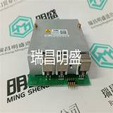
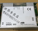
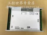
易卖工控网(www.ymgk.com)提供”0240-63968-501520模块备件”,产品详情:品牌/厂家:0040-32460-504815、型号:0240-63968-501520、成色:全新、货期:现货 1天内发货、保修:180天,更多产品详情就上易卖工控网。
0240-63968-501520
一个CPU是总线上的主CPU,
所有其他远程单元或CPU被视为
奴隶。
主CPU多管理31个远程
一条总线上的单元。
所有消息都会通过错误检查(CRC8)终止。
消息的格式:
-来自主CPU的请求
地址数据CRC8
-远程装置的响应
启动数据CRC8
在初始化期间,中央单元询问所有
远程单位相继出现,从而树立了
系统配置。
在总线的每个周期上,所有远程单元都是
被审问。
这将更新所有诊断信息并识别
其他远程装置。
如果CPU或其中一个远程单元收到消息
如果出现(CRC8)错误,则忽略该错误。
连续十次传输错误后,错误“总线
远程装置和
中央单元的诊断。
1.2传输格式
ABB Procontic CS31/版本:11.96-FRCTL 2 1.3-1总线刷新时间
1.3总线刷新时间
刷新时间取决于系统配置、远程单元的数量和类型。
以下示例适用于远程装置类型的系统
ICSC 08 L1:
执行用户程序和总线刷新周期
在意甲,07 KR/KT 31,07 KR 91和07 KT 92/93
中央单元。时间事件图如下所示:
● 总线刷新时间(T rb)
总线传输时间很容易从
安装的配置。
该时间等于:
–配备主中央单元Series 90:
T rb=T偏移量+T通信时间
–配备主中央单元serie 30:
T rb=T偏移量+T通信时间+n*100(µs)
使用:
–T偏移=2000µs
–T通信时间:见下页表格
–n=总线上的从机数量
计算示例
配置:
1“主”CPU。。。。。。。。。2000µs
1 ICSK 20 F1。。。。。。。。。。。。。。。。452µs
1 ICSO 08 R1。。。。。。。。。。。。。。。260µs
1 ICSI 16 E1。。。。。。。。。。。。。。。。。387µs
1 ICFC 16 L1。。。。。。。。。。。。。。。。516µs
1 ICSC 08 L1。。。。。。。。。。。。。。。。387µs
–配备主中央单元serie 90
T rb=4 002µs=4 ms
–配备主中央单元serie 30
T rb=4 502µs=4,5 ms
● 为来自的输出通电的响应时间
激活输入
参见3部分5.3-1页,了解主中央单元系列30。
请参阅4部分1-22页或2-25页或3-21页,了解master central
单元90系列。
C 226 D
2毫秒
12毫秒
时间
数字
单位数量
C 227
外部的
均衡
阅读
输入的数量
公共汽车
传输
程序
处决
公共汽车
传输
输入延迟:2到32毫秒
1.5至12毫秒(二进制模块)
多2个周期
已编程
1.5至12毫秒(二进制模块)
2总线刷新时间1.3-2 ABB Procontic CS31/版本:11.96-FRCTL
通信时间
偏移时间主CPU 2000µs
从属中央单元
07 KR 31*750µs
07节31*750µs
07 KR 91*750µs
07节92*750µs
07节93*750µs
*出厂设置
配置后的时间:
传输中有2个字节
接收516µs时为2字节
传输中有4个字节
接收750µs时为4字节
传输中的8字节
接收1300µs时为8字节
传输12字节
接收1850µs时为12字节
8字传输
接收2500µs时8个字
二进制输入单元
ICSI 08 D1 323µs
ICSI 08 E1 323µs
ICSI 08 E3/E4 323µs
ICSI 16 D1 387µs
ICSI 16 E1 387µs
二进制输出单元
ICSO 08 R1 260µs
ICSO 08 Y1 260µs
ISCO 16 N1 340µs
二进制输入/输出单元
ICSC 08 L1 387µs
ICFC 16 L1 516µs
ICSK 20 F1 452µs
ICSK 20 N1 452µs
ICDG 32 L1 516/590µs
遵循配置
IP65二进制输入/输出单元
ICPI 08 D1 323µs
ICPI 16 D1 387µs
ICPO 08 H1 260µs
ICPO 16 H1 340µs
Aniaogue单位
ICSM 06 A6(输入/输出)1162µs
ICSE 08 A6(输入)1355µs
ICSE 08 B5(输入)1355µs
ICST 08 A7(输入)1355µs
ICST 08 A8(输入)1355µs
ICST 08 A9(输入)1355µs
ICDT 08 B5(输入)1355µs
ICSA 04 B5(输出)700µs
机器人连接器卡
ICBG 32 L7 516µs
ICBG 64 L7 750µs
高速计数器
ICSF 08 D1 1300µs
ABB Procontic CS31/版本:11.96-FRCTL 2 1.4-1尺寸
H
W
D
D
H
W
H1
W1
0
7.
1.
6 5 4 3 2
D
H
W
H1
W1
1.4尺寸
类型简短描述尺寸(mm)
带单元载波/终端
宽x高x深
W1 x H1 x D1
07 KR 91
07 KT 92中央处理单元240 x 140 x 85 07 KT 93–07 SA 93定位单元
07 KR 31中央处理器120 x 60 x 115
07节31 123 x 64
ICS。。二进制或模拟单元120 x 60 x 115输入-输出-输入/输出123 x 64高速计数器单元
244 x 60 x 80
ICFC 16 L1二进制输入/输出单元246 x 64
ECZ插件底座123 x 64 x 30
ICD。。二进制或模拟远程单元120 x 140 x 85
– –
ICPI 16 D1二进制远程装置(IP 65保护)367 x 78 x 78.5 ICPO 16 H1–-
ICPI 08 D1二进制远程装置(IP 65保护)247 x 78 x 78.5 ICPO 08 H1–-
07 KP 90
07 KP 92通信耦合器120 x 140 x 85
07 MK 92–
NCC 232
NCC 485通信附件120 x 80 x 85 NCB–NCBR
TCAD文本显示230 x 80 x 47
198 x 67 x 42
其他产品(ICBG 32L7型、ICBG 64L7型、07CS61型、07CM90型)安装在机架中。
其尺寸取决于
0240-63968-501520
0240-63968-501520
One single CPU is the master on the bus, all of the other remote units or CPU are considered to be slaves. The master CPU manages up to a maximum of 31 remote units on one bus. All messages are terminated with an error check (CRC8). The format of the messages : - request from the master CPU Address Data CRC8 - response from the remote units Start Data CRC8 During initialization, the central unit interrogates all of the remote units in succession, thus building an image of the system configuration. On each cycle of the bus all of the remote units are interrogated. This updates all diagnosis information and recognizes additional remote units. If the CPU or one of the remote units receives a message with a (CRC8) error, it is ignored. After ten consecutive transmission errors, an error "Bus error" is generated on the remote units and within the diagnosis of the central unit. 1.2 Transmission format ABB Procontic CS31/Edition : 11.96 - FRCTL 2 1.3-1 Bus refresh time 1.3 Bus refresh time The refresh time depends on the configuration of the system, number and type of remote units. The example below is for a system of remote units type ICSC 08 L1 : The user program and the bus refresh cycle are executed in serie with the 07 KR/KT 31, 07 KR 91 and 07 KT 92/93 central units. The time event diagram is shown below : ● Bus refresh time (T rb) The bus transmission time is easily calculated from the configuration of the installation. This time is equal to : – with a master central unit serie 90 : T rb = T offset + T communication time – with a master central unit serie 30 : T rb = T offset + T communication time + n * 100 (µs) with : – T offset = 2 000 µs – T communication time : see table on the next page – n = number of slaves on the bus Example of calculation Configuration : 1 "Master" CPU .........2 000 µs 1 ICSK 20 F1................452 µs 1 ICSO 08 R1 ............... 260 µs 1 ICSI 16 E1 ................. 387 µs 1 ICFC 16 L1 ................516 µs 1 ICSC 08 L1................387 µs – with a master central unit serie 90 T rb = 4 002 µs = 4 ms – with a master central unit serie 30 T rb = 4 502 µs = 4,5 ms ● Response time to energize an output from the activation of an input See Part 3 page 5.3-1 for a master central unit serie 30. See Part 4 pages 1-22 or 2-25 or 3-21 for a master central unit serie 90. C 226 D 2 ms 12 ms Time Number of units C 227 External evenement Reading of input Bus transmission Program execution Bus transmission Input delay: 2 to 32 ms 1.5 to 12 ms (binary module) Max. 2 cycles programmed 1.5 to 12 ms (binary module) 2 Bus refresh time 1.3-2 ABB Procontic CS31/Edition : 11.96 - FRCTL Communication time offset time Master CPU 2000 µs Slave central units 07 KR 31* 750 µs 07 KT 31* 750 µs 07 KR 91* 750 µs 07 KT 92 * 750 µs 07 KT 93 * 750 µs * with factory setting time following the configuration : 2 bytes in transmission 2 bytes in receiving 516 µs 4 bytes in transmission 4 bytes in receiving 750 µs 8 bytes in transmission 8 bytes in receiving 1300 µs 12 bytes in transmission 12 bytes in receiving 1850 µs 8 words in transmission 8 words in receiving 2500 µs Binary input units ICSI 08 D1 323 µs ICSI 08 E1 323 µs ICSI 08 E3/E4 323 µs ICSI 16 D1 387 µs ICSI 16 E1 387 µs Binary output units ICSO 08 R1 260 µs ICSO 08 Y1 260 µs ISCO 16 N1 340 µs Binary input/output units ICSC 08 L1 387 µs ICFC 16 L1 516 µs ICSK 20 F1 452 µs ICSK 20 N1 452 µs ICDG 32 L1 516/590 µs following the configuration IP65 binary input/output units ICPI 08 D1 323 µs ICPI 16 D1 387 µs ICPO 08 H1 260 µs ICPO 16 H1 340 µs AnaIogue units ICSM 06 A6 (input/output) 1162 µs ICSE 08 A6 (input) 1355 µs ICSE 08 B5 (input) 1355 µs ICST 08 A7 (input) 1355 µs ICST 08 A8 (input) 1355 µs ICST 08 A9 (input) 1355 µs ICDT 08 B5 (input) 1355 µs ICSA 04 B5 (output) 700 µs Robot coupler card ICBG 32 L7 516 µs ICBG 64 L7 750 µs High speed counter ICSF 08 D1 1300 µs ABB Procontic CS31/Edition : 11.96 - FRCTL 2 1.4-1 Dimensions H W D D H W H1 W1 0 7 1 6 5 4 3 2 D H W H1 W1 1.4 Dimensions Types Short description Dimensions in mm with unit carrier/ terminal W x H x D W1 x H1 x D1 07 KR 91 07 KT 92 Central processing units 240 x 140 x 85 07 KT 93 – – 07 SA 93 Positioning unit 07 KR 31 Central processing units 120 x 60 x 115 07 KT 31 123 x 64 ICS.. Binary or analog units 120 x 60 x 115 Input - Output - Input/Output 123 x 64 High speed counter unit 244 x 60 x 80 ICFC 16 L1 Binary Input/Output unit 246 x 64 ECZ Plug-in base 123 x 64 x 30 ICD.. Binary or analog remote units 120 x 140 x 85 – – ICPI 16 D1 Binary remote units (IP 65 protection) 367 x 78 x 78.5 ICPO 16 H1 – – ICPI 08 D1 Binary remote units (IP 65 protection) 247 x 78 x 78.5 ICPO 08 H1 – – 07 KP 90 07 KP 92 Communication couplers 120 x 140 x 85 07 MK 92 – – NCC 232 NCC 485 Communication accessories 120 x 80 x 85 NCB – – NCBR TCAD Text display 230 x 80 x 47 198 x 67 x 42 The other products (type ICBG 32L7, type ICBG 64L7, type 07CS61, type 07CM90) are mounted in a rack. Their dimensions depend on their ranges (Robot S3, ABB Procontic T 200 and PC). W D H W1 W D1 H1 D H D H W H W D W D H D H1 W1 D H W W1 H1 1.5- 1 2 ABB Procontic CS31/Edition : 11.96 - FRCTL Approvals and classification 1.5 Approvals and classification societies The product listed in the catalogue is designed according to the relevant standards; it is manufactured and tested under our owwn reponsability. The table below indicates for each unit the situation regarding the approvals for those countries or with regard to the classification societies where an approval is mandatory and confirms that products in standard version can be used worldwide thus avoiding double stocking. All following units are developped, tested and produced according to the standard IEC 1131-2. UL : only for 24 VDC and 120 VAC versions. Ships classification societies agreements for : 24 VDC, 120 and 230 VAC versions. ■ : approved ▲ : applied in 1996 Unit Approvals Ships classification societies agreements type Test mark Abbreviation UL CSA BV GL LRS MRS RINa DNV ABS Approved in USA Canada France German. Gr.Brit. Russia Italy Norway USA CS 31 CPU 07 KR 31 ■ ■ ■ ■ ■■ ■ ■ 07 KT 31 ▲ ■ ■ ■ ■■ ■ ■ 07 KR 91 ■ ■ ■ ■ ■ ■■ ■ ■ 07 KT 92 ■ ■ ■ ■ ■ ■■ ■ ■ 07 KT 93 ■ ■ ■ ■ ■ ■■ ■ ■ CS 31 remote units ICSI 08 D1 ■ ■ ■ ■ ■■ ■ ■ ICSI 08 E1 ■ ■ ■ ■ ■■ ■ ■ ICSI 16 D1 ■ ■ ■ ■ ■■ ■ ■ ICSI 16 E1 ■ ■ ■ ■ ■■ ■ ■ ICSI 08 E3 ■ ■ ■ ■ ■■ ■ ■ ICSI 08 E4 ■ ■ ■ ■■ ■ ■ ICSO 08 R1 ■ ■ ■ ■ ■■ ■ ■ ICSO 08 Y1 ICSO 16 N1 ▲ ■ ■ ■ ■■ ■ ■ ICSC 08 L1 ▲ ■ ■ ■ ■■ ■ ■ ICFC 16 L1 ▲ ■ ■ ■ ■■ ■ ■ ICSK 20 F1 ■ ■ ■ ■ ■■ ■ ■ ICSK 20 N1 ▲ ■ ■ ■ ■■ ■ ■ ICDG 32 L1 ■ ■ ■ ■ ■ ■■ ■ ■ ICSF 08 D1 ■ ■ ■ ■ ■■ ■ ■ ICPI 08 D1 ■■■ ■ ICPI 16 D1 ■■■ ■ ICPO 08 H1 ■■■ ■ ICPO 16 H1 ■■■ ■ All products have CE marking. Unit Approvals Ships classification societies agreements type Test mark Abbreviation UL CSA BV GL LRS MRS RINa DNV ABS Approved in USA Canada France German. Gr.Brit. Russia Italy Norway USA CS 31 remote units ICSE 08 A6 ■ ■ ■ ■ ■■ ■ ■ ICSE 08 B5 ■ ■ ■ ■ ■■ ■ ■ ICST 08 A7 ICST 08 A8 ■ ■ ■ ■ ■■ ■ ■ ICST 08 A9 ■ ■ ■ ■ ■■ ■ ■ ICSA 04 B5 ■ ■ ■ ■ ■■ ■ ■ ICSM 06 A6 ■ ■ ■ ■ ■■ ■ ■ ICDT 08 B5 ■ ■ ■ ■ ■ ■■ ■ ■ CS31 other units and accessories TCAD ▲ ■ ■ ■ ■■ ■ ■ NCB ▲ ■ ■ ■ ■■ ■ ■ NCBR ▲ ■ ■ ■ ■■ ■ ■ ICBG 32 L7 ICBG 64 L7 07 KP 90 ■ ■ ■ ■ ■ ■■ ■ ■ 07 KP 92 ■ ■ ■ ■ ■ ■■ ■ ■ NCC 232 ▲ ■ ■ ■ ■■ ■ ■ NCC 485 ▲ ■ ■ ■ ■■ ■ ■ ECZ ■ ■ ■ ■ ■■ ■ ■ CS 31 coupler for T200 07 CS 61 ■ ■ ■ ■ ■ ■■ ■ ■ 2 ABB Procontic CS31/Edition : 11.96 - FRCTL 2-1 Central units Chapter Description Page 2.1 07 KR 31 2.1-1 2.2 07 KT 31 2.2-1 2.3 07 KR 91 2.3-1 2.4 07 KT 92 2.4-1 2.5 07 KT 93 2.5-1 2.6 07 GV 93 2.6-1 2.7 UCZA/UCZB 2.7-1 2.8 PCZB 2.8-1 2.9 CS20 2.9-1 2 Contents Central units 2 ABB Procontic CS31/Edition : 11.95 - FRCTL 2.1-1 07 KR 31 2.1 07 KR 31 Central unit 2 k instructions The comprehensive description for this central unit is located in part 3 of this volume. Brief description The central unit 07 KR 31 works either as ● Bus master in the decentralized automation system ABB Procontic CS31 or as ● Slave (remote processor) in the decentralized automation system ABB Procontic CS 31 or as ● Stand-alone central unit. The unit is provided in three versions with supply voltages of 24 V DC, 120 V AC or 230 V AC : The central unit versions have the following main features : ● 12 binary inputs ● 8 binary relay outputs ● 1 counting input for couting frequencies up to 10 kHz ● 1 CS31 system bus interface for system expansion ● Serial interface COM1 – is set as programming interface – can be set as an ASCII interface for connecting peripheral devices (e.g. MMC devices) – can be set as MODBUS interface ● has a built-in MODBUS protocol (master and slave) ● Real-time clock ● LEDs for displaying the binary input and output signals as well as operating conditions and error messages ● Fastening by inserting in the plug-in base ECZ. The plug-in base can either be snapped on a DIN rail or fastened by screws. ● Built-in lithium battery for back-up of the RAM contents, its lifetime is 10 years. ● Reading and writing program protection by password ● Programming with the programming software 907 PC 331 ● "On-Line" programming ● User program containing max. 2 k of instructions ● RUN/STOP switch for starting and aborting the program execution ● Extensive diagnosis functions – Self-diagnosis of the central unit – Diagnosis of the ABB Proncontic CS31 system bus and the connected units SUPPLY INPUT OUTPUT 62,00 01 02 03 04 05 06 07 08 09 10 11 07KR31 24VDC 5W CENTRAL UNIT ABB Procontic CS 31 STOP RUN RUN C 111 D/2 Central unit 07 KR 31 2 ABB Procontic CS31/Edition : 01.95 - FRCTL 2.2-1 07 KT 31 2.2 07 KT 31 Central unit 2 k instructions The comprehensive description for this central unit is located in part 3 of this volume. Brief description The central unit 07 KT 31 works either as ● Bus master in the decentralized automation system ABB Procontic CS31 or as ● Slave (remote processor) in the decentralized automation system ABB Procontic CS 31 or as ● Stand-alone central unit. The unit is provided in three versions with supply voltages of 24 V DC, 120 V AC or 230 V AC : The central unit versions have the following main features : ● 12 binary inputs ● 8 binary transistor 24VDC/0.5A outputs ● 1 counting input for couting frequencies up to 10 kHz ● 1 CS31 system bus interface for system expansion ● Serial interface COM1 – is set as programming interface – can be set as an ASCII interface for connecting peripheral devices (e.g. MMC devices) – can be set as MODBUS interface C 202 D Central unit 07 KT 31 SUPPLY INPUT OUTPUT 62,00 01 02 03 04 05 06 07 08 09 10 11 07KT31 24VDC 5W CENTRAL UNIT ABB Procontic CS 31 STOP RUN RUN ● has a built-in MODBUS protocol (master and slave) ● Real-time clock ● LEDs for displaying the binary input and output signals as well as operating conditions and error messages ● Fastening by inserting in the plug-in base ECZ. The plug-in base can either be snapped on a DIN rail or fastened by screws. ● Built-in lithium battery for back-up of the RAM contents, its lifetime is 10 years. ● Reading and writing program protection by password ● Programming with the programming software 907 PC 331 ● "On-Line" programming ● User program containing max. 2 k of instructions ● RUN/STOP switch for starting and aborting the program execution ● Extensive diagnosis functions – Self-diagnosis of the central unit – Diagnosis of the ABB Proncontic CS31 system bus and the connected units 2 ABB Procontic CS31/Edition : 11.94 - FRCTL 2.3-1 07 KR 91 2.3 07 KR 91 Central unit 7 k instructions The comprehensive description for this central unit is located in part 4 of this volume. The same description is available as an operating manual, order No. GATS 1316 01 R2001. Brief description The central unit 07 KR 91 works either as ● Bus master in the decentralized automation system ABB Procontic CS31 or as ● Slave (remote processor) in the decentralized automation system ABB Procontic CS 31 or as ● Stand-alone central unit. The module is provided in two versions with supply voltages of 24 V DC and 115/230 V AC : 07 KR 91 R101 : The device has a 115/230 V AC power supply voltage. It provides a 24 V output voltage for the supply of its own binary inputs. 07 KR 91 R151 : The device has a 24 V DC power supply voltage. It is provided with an additional interface for connecting communication modules (e.g. 07 KP 90). Both module versions have the following main features : ● 20 binary inputs ● 12 binary relay outputs ● 1 counting input for couting frequencies up to 10 kHz ● Central unit for an user program containing ma. 7 k of instructions ● 1 CS31 system bus interface for system expansion ● Serial interface COM1 – is set as programming interface – can be set as an ASCII interface for connecting peripheral devices (e.g. MMC devices) ● Real-time clock ● LEDs for displaying the binary input and output signals as well as operating conditions and error messages ● Detachable screw-type terminal blocks ● Detachable plastic sheet on the front side of the device ; can be labelled with the signal names in order to have the inputs and outputs directly assigned ● Fastening by screws or by snapping the device on a DIN rail ● The lithium battery 07 LE 90 can be put into the battery compartment in order to – store and back-up the user program in the RAM – store and back-up data which is additionally contained in the RAM, e.g. the status of flags – back-up the time and date (real-time clock) ● RUN/STOP switch for starting and aborting the program execution ● Extensive diagnosis functions – Self-diagnosis of the central unit – Diagnosis of the ABB Proncontic CS31 system bus and the connected modules Central unit 07 KR 91 ABB Procontic CS31 07 KR 91 C 151 D 2 ABB Procontic CS31/Edition : 11.94 - FRCTL 2.4-1 07 KT 92 2.4 07 KT 92 Central unit 7 k instructions The comprehensive description for this central unit is located in part 4 of this volume. The same description is available as an operating manual, order No. GATS 1316 02 R2001. Brief description The central unit 07 KT 92 works either as ● bus master in the decentralized automation system ABB Procontic CS31 or as ● slave (remote processor) in the decentralized automation system ABB Procontic CS31 or as ● stand-alone central unit. Main features ● Power supply 24 V DC ● 12 binary inputs ● 8 binary transistor outputs ● 4 analog inputs ● 1 analog output ● 1 calibrated 10 V output ● 1 counting input for counting frequencies up to 10 kHz ● Central unit for a user program containing max. 7 k of instructions ● 1 CS31 system bus interface for system expansion ● Serial interface COM1 – is set as programming interface – can be set as an ASCII interface for connecting peripheral devices (e.g. MMC devices) ● Serial interface COM2 as an MMC interface ● Additional interface for connecting communication modules (e.g. 07 KP 90) ● Real-time clock ● LEDs for displaying the binary input and output signals as well as operating conditions and error messages ● Detachable screw-type terminal blocks ● Detachable plastic sheet on the front side of the device ; can be labelled with the signal names in order to have the inputs and outputs directly assigned ● Fastening by screws or by snapping the device on a DIN rail ● The lithium battery 07 LE 90 can be put into the battery compartment in order to – store and back-up the user program in the RAM – store and back-up data which is additionally contained in the RAM, e.g. the status of flags – back-up the time and date (real-time clock) ● RUN/STOP switch for starting and aborting the program execution ● Extensive diagnosis functions – Self-diagnosis of the central unit – Diagnosis of the ABB Pro


闽公网安备 35020302034948号


 收藏商品
收藏商品

 QQ咨询
QQ咨询
 当前商品暂无此评价~


 2778087246
 18150367963


 记住账号
记住账号
