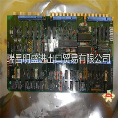
易卖工控网(www.ymgk.com)提供”F03-105962-504535模块备件”,产品详情:品牌/厂家:、型号:F03-105962-504535、成色:全新、货期:现货 1天内发货、保修:180天,更多产品详情就上易卖工控网。
F03-105962-504535
前言
本手册解释了如何使用霍纳APG的电阻温度设备输入模块。
版权所有(C)2005 Horner APG,LLC,640 North Sherman Drive,Indianapolis,Indiana 46201。所有权利
保留。本出版物的任何部分不得在检索中复制、传输、转录或存储
系统,或以任何形式通过任何方式翻译成任何语言或计算机语言,电子,
机械、磁性、光学、化学、手动或其他,未经事先同意和书面同意
霍纳APG有限责任公司的许可。
本文件或媒体中描述的所有软件也是受条款和
霍纳软件许可协议的条件。
本文件中的信息如有更改,恕不另行通知,并不代表对以下事项的承诺:
霍纳APG有限责任公司的一部分。
LogicMaster是GE Fanuc的商标。
有关用户手册更新,请联系Horner APG,技术支持
电话:(317)916-4274或访问我们的网站www.heapg。通用域名格式。
4页2014年8月20日MAN0073-12
有限保证和责任限制
Horner APG,LLC,Inc.(“HE”)向原买方保证,电阻温度装置
HE制造的输入模块在正常使用下没有材料和工艺缺陷
和服务。HE在本保证项下的义务应限于维修或更换任何
自日期起两(2)年内,在正常使用和服务下可能证明有缺陷的一个或多个零件
由原买方制造或自安装之日起十八(18)个月,以两者为准
首先发生的情况下,该缺陷应在其检查后披露,并使其满意
有缺陷的零件。本保证明确代替所有其他保证
明示或暗示,包括适销性和适用性保证
使用和所有其他义务或责任,且他既不承担,也不
授权任何其他人为其承担任何其他相关责任
随着这种电阻温度装置输入模块的销售。本保证应
不适用于该电阻温度装置输入模块或其任何部分
受到事故、疏忽、更改、滥用或误用的影响。他
对于不符合以下条件的附件或零件不作任何保证:
由HE提供。本保修中使用的术语“原始买方”应为:
被视为是指电阻温度装置输入模块的用户
初安装。本保证仅在以下范围内适用:
美国大陆。
在任何情况下,无论是由于违反合同、保证、侵权行为(包括疏忽)或其他原因,
其或其供应商应承担任何特殊、后果性、偶然或刑事损害赔偿责任,包括:,
但不限于利润或收入损失、产品或任何相关设备的使用损失,
相关设备的损坏、资本成本、替代产品、设施、服务的成本或
更换电源、停机时间成本或原买方客户对此类损害的索赔。
要获得保修服务,请将产品退还给您的经销商,并附上以下说明:
问题、购买证明、邮费、保险和合适的包装。
关于编程示例
本手册中或随附磁盘上提供的任何示例程序和程序段包括:
仅用于说明目的。由于与任何
对于特定安装,霍纳APG不承担基于
示例和图表。利用阻力的系统设计师全权负责
温度设备输入模块适当设计终端系统,适当集成
电阻温度装置输入模块,并按原样为终端设备制定安全规定
适用的任何规范或标准中定义的工业应用中的常见和习惯。
注:本手册中所示的编程示例仅供说明
只有正确操作机器是系统集成商的责任。1章:说明
1.1产品描述
1.1.1 RTD输入模块允许RTD温度传感器直接连接到PLC
无外部信号处理(传感器、发射器等)。所有模拟和数字处理
RTD信号在模块上执行,温度值以0.5°C或0.5°F为增量
(RTD600)或0.125°C、0.1°C或0.1°F(RTD601)增量写入90-30%AI输入表。全部的
模块具有六个通道,支持PT-90(MIL-7990);PT-100E、PT-100C和PT-100Z;Ni-120,
Cu-10、Cu-50、Cu-53、Cu-100、Pt-1000、TD5R和线性电阻。
图1.1-前视图
8页2014年8月20日MAN0073-12
1.2规范
表1.1-HE693RTD600/601规范
耗电量
(典型)75mA@5VDC通道数6
类型
支持支持
Pt-100E
alpha=。00385-100至850需要6%AI的C输入/输出点
Pt-100C
alpha=。003902-100至650C输入阻抗>1000兆欧
Pt-100Z
alpha=。03906-200至300C故障保护齐纳二极管钳位
Pt-1000-100至850C A/D转换类型16位,积分
Cu-10-200至260C更新时间每秒50个通道
Cu-50 0至100C
平均RTD电流,
PT-100 330微安
Cu-53-200至260C
通道到通道
跟踪0.1C
Cu-100-200至200C分辨率0.5C或0.5F
0.125C
0.1C、 或0。
1.F
Ni-120-100至270C精度
0.5C典型,
1C用于Cu-10和
TD5R
线性0到200 工作温度0至60C(32 至140F)
TD5R-40至150C相对湿度5%-95%无冷凝
Pt-90
(MIL-7990)-50至200C
平台支持
(硬件版本)
R版和
先前的
后来
修订
90-30仅90-30和
RX3i
平台
图1.2–侧视图
MAN0073-12 2014年8月20日9页
2章:配置
2.1概述
2.1.1二章描述了使用LogicMaster进行输入/输出配置的程序和设置
软件
2.2配置
1、进入LogicMaster时 90软件,选择“LogicMaster Configuration Package”(F2)
从菜单中。
2.要进入配置屏幕,请从菜单中选择“输入/输出配置”(F1)
图2.1–默认屏幕
图2.2–配置屏幕
10页2014年8月20日MAN0073-12
3.将光标移动到包含模块的指定插槽,然后选择“其他”(F8)。
4.从以下屏幕中,选择“国外”(F3)。
图2.3–机架配置
图2.4–插槽配置
MAN0073-12 2014年8月20日11页
5.屏幕(如图2.5所示)应出现:
2.2.1配置参数
2.2.1.1表2.1和2.2显示了配置HE693RTD600和
HE693RTD601。参数包括%AI大小、字节1、字节2、字节3和字节4。
2.2.1.2更改各种字节(1-4),并将%AI设置为“6”,以达到所需设置。
表2.1-RTD 600的配置参数
%AI大小字节1字节2字节3字节4
6 0001
0000
通过
0111
(见图表)
00=Pt-100E
00=0.5C
01=0.5F
01=Ni-120
02=Pt-100C
03=Cu-10
04=LIN100
05=Pt-1000
06=TD5R
07=Pt-100Z
08=Cu-50
09=Cu-53
0A=Cu-100
0B=Pt-90
图2.5–模块配置
12页2014年8月20日MAN0073-12
表2.2-RTD601的配置参数
%AI大小字节1字节2字节3字节4
6 0001
0000
通过
0111
(见图表)
00=Pt-100E
00=0.125C
01=0.1C
02=0.1F
01=Ni-120
02=Pt-100C
03=Cu-10
04=LIN100
05=Pt-1000
06=TD5R
07=Pt-100Z
08=Cu-50
09=Cu-53
0A=Cu-100
0B=Pt-90
2.2.2数字滤波
2.2.2.1数字滤波(在HE693RTD600/601模块上)对温度的响应效果
变化如图2.6所示。(%温度变化完成vs.时间)。字节2设置
数字滤波量。
0
10
20
30
40
50
60
70
80
90
100
图2.6-数字滤波的效果
MAN0073-12 2014年8月20日13页
2.2.3温度定标
2.2.3.1电阻温度装置在0.5、0.125或0.1中向%AI表报告值
以任何一种方式递增C或F、 可以使用表2.3计算到实际度数的转换。
注:模块配置取决于分配给字节4的参数。
表2.3-温度标度
单元
配置
温度
转变
0.5CC=%AI/2
0.5FF=%AI/2
0.125CC=%AI/8
0.1CC=%AI/10
0.1FF=%AI/10
LIN100每1个报告128个计数.
示例:
如果%AI2等于RTD模块上的通道2,%AI2等于1000,则温度读数为
T=100C(格式1C) 。
如果%ai2等于1000,字节4等于00.125C或1/8),温度为T=125C
14页2014年8月20日MAN0073-12
笔记
MAN0073-12 2014年8月20日15页
3章:接线和安装
3.1 RTD接线板连接的接线图
图3.1-接线图
北卡罗来纳州
16页2014年8月20日MAN0073-12
3.1.1三线连接
3.1.1.1图3.2显示了如何与RTD模块进行三线连接。
(参见图3.1。)
3.1.2双线连接
3.1.2.1图3.3显示了如何与RTD模块进行双线连接。
(参见图3.1。)
注:支持双线RTD,但精度可能会有所不同。
不支持四线RTD
3.2安装要求
a、 布线应在其自己的导管中进行。
屏蔽、绞合接线提供了佳的抗噪性。
c、 如果使用屏蔽接线,良好的接地连接(仅在一端)至关重要。
c、 如果在模块端连接屏蔽,端子1或20可用作屏蔽接地
指向
d、 每条导线的引线电阻应不大于50.
e、 所有未使用的通道应短接在一起,并连接到引脚1或20。
F03-105962-504535
F03-105962-504535
PREFACE This manual explains how to use the Horner APG’s Resistance Temperature Device Input Module. Copyright (C) 2005 Horner APG, LLC, 640 North Sherman Drive, Indianapolis, Indiana 46201. All rights reserved. No part of this publication may be reproduced, transmitted, transcribed, stored in a retrieval system, or translated into any language or computer language, in any form by any means, electronic, mechanical, magnetic, optical, chemical, manual or otherwise, without the prior agreement and written permission of Horner APG, LLC. All software described in this document or media is also copyrighted material subject to the terms and conditions of the Horner Software License Agreement. Information in this document is subject to change without notice and does not represent a commitment on the part of Horner APG, LLC. LogicMaster is a trademark of GE Fanuc. For user manual updates, contact Horner APG, Technical Support Division, at (317) 916-4274 or visit our website at www.heapg.com. PAGE 4 20 AUG 2014 MAN0073-12 LIMITED WARRANTY AND LIMITATION OF LIABILITY Horner APG, LLC, Inc. ("HE") warrants to the original purchaser that the Resistance Temperature Device Input module manufactured by HE is free from defects in material and workmanship under normal use and service. The obligation of HE under this warranty shall be limited to the repair or exchange of any part or parts which may prove defective under normal use and service within two (2) years from the date of manufacture or eighteen (18) months from the date of installation by the original purchaser whichever occurs first, such defect to be disclosed to the satisfaction of HE after examination by HE of the allegedly defective part or parts. THIS WARRANTY IS EXPRESSLY IN LIEU OF ALL OTHER WARRANTIES EXPRESSED OR IMPLIED INCLUDING THE WARRANTIES OF MERCHANTABILITY AND FITNESS FOR USE AND OF ALL OTHER OBLIGATIONS OR LIABILITIES AND HE NEITHER ASSUMES, NOR AUTHORIZES ANY OTHER PERSON TO ASSUME FOR HE, ANY OTHER LIABILITY IN CONNECTION WITH THE SALE OF THIS Resistance Temperature Device Input module. THIS WARRANTY SHALL NOT APPLY TO THIS Resistance Temperature Device Input module OR ANY PART THEREOF WHICH HAS BEEN SUBJECT TO ACCIDENT, NEGLIGENCE, ALTERATION, ABUSE, OR MISUSE. HE MAKES NO WARRANTY WHATSOEVER IN RESPECT TO ACCESSORIES OR PARTS NOT SUPPLIED BY HE. THE TERM "ORIGINAL PURCHASER", AS USED IN THIS WARRANTY, SHALL BE DEEMED TO MEAN THAT PERSON FOR WHOM THE Resistance Temperature Device Input module IS ORIGINALLY INSTALLED. THIS WARRANTY SHALL APPLY ONLY WITHIN THE BOUNDARIES OF THE CONTINENTAL UNITED STATES. In no event, whether as a result of breach of contract, warranty, tort (including negligence) or otherwise, shall HE or its suppliers be liable of any special, consequential, incidental or penal damages including, but not limited to, loss of profit or revenues, loss of use of the products or any associated equipment, damage to associated equipment, cost of capital, cost of substitute products, facilities, services or replacement power, down time costs, or claims of original purchaser's customers for such damages. To obtain warranty service, return the product to your distributor with a description of the problem, proof of purchase, post paid, insured and in a suitable package. ABOUT PROGRAMMING EXAMPLES Any example programs and program segments in this manual or provided on accompanying diskettes are included solely for illustrative purposes. Due to the many variables and requirements associated with any particular installation, Horner APG cannot assume responsibility or liability for actual use based on the examples and diagrams. It is the sole responsibility of the system designer utilizing the Resistance Temperature Device Input module to appropriately design the end system, to appropriately integrate the Resistance Temperature Device Input module and to make safety provisions for the end equipment as is usual and customary in industrial applications as defined in any codes or standards which apply. Note: The programming examples shown in this manual are for illustrative purposes only. Proper machine operation is the sole responsibility of the system integrator.PREFACE
This manual explains how to use the Horner APG’s Resistance Temperature Device Input Module.
Copyright (C) 2005 Horner APG, LLC, 640 North Sherman Drive, Indianapolis, Indiana 46201. All rights
reserved. No part of this publication may be reproduced, transmitted, transcribed, stored in a retrieval
system, or translated into any language or computer language, in any form by any means, electronic,
mechanical, magnetic, optical, chemical, manual or otherwise, without the prior agreement and written
permission of Horner APG, LLC.
All software described in this document or media is also copyrighted material subject to the terms and
conditions of the Horner Software License Agreement.
Information in this document is subject to change without notice and does not represent a commitment on
the part of Horner APG, LLC.
LogicMaster is a trademark of GE Fanuc.
For user manual updates, contact Horner APG, Technical Support
Division, at (317) 916-4274 or visit our website at www.heapg.com.
PAGE 4 20 AUG 2014 MAN0073-12
LIMITED WARRANTY AND LIMITATION OF LIABILITY
Horner APG, LLC, Inc. ("HE") warrants to the original purchaser that the Resistance Temperature Device
Input module manufactured by HE is free from defects in material and workmanship under normal use
and service. The obligation of HE under this warranty shall be limited to the repair or exchange of any
part or parts which may prove defective under normal use and service within two (2) years from the date
of manufacture or eighteen (18) months from the date of installation by the original purchaser whichever
occurs first, such defect to be disclosed to the satisfaction of HE after examination by HE of the allegedly
defective part or parts. THIS WARRANTY IS EXPRESSLY IN LIEU OF ALL OTHER WARRANTIES
EXPRESSED OR IMPLIED INCLUDING THE WARRANTIES OF MERCHANTABILITY AND FITNESS
FOR USE AND OF ALL OTHER OBLIGATIONS OR LIABILITIES AND HE NEITHER ASSUMES, NOR
AUTHORIZES ANY OTHER PERSON TO ASSUME FOR HE, ANY OTHER LIABILITY IN CONNECTION
WITH THE SALE OF THIS Resistance Temperature Device Input module. THIS WARRANTY SHALL
NOT APPLY TO THIS Resistance Temperature Device Input module OR ANY PART THEREOF WHICH
HAS BEEN SUBJECT TO ACCIDENT, NEGLIGENCE, ALTERATION, ABUSE, OR MISUSE. HE
MAKES NO WARRANTY WHATSOEVER IN RESPECT TO ACCESSORIES OR PARTS NOT
SUPPLIED BY HE. THE TERM "ORIGINAL PURCHASER", AS USED IN THIS WARRANTY, SHALL BE
DEEMED TO MEAN THAT PERSON FOR WHOM THE Resistance Temperature Device Input module IS
ORIGINALLY INSTALLED. THIS WARRANTY SHALL APPLY ONLY WITHIN THE BOUNDARIES OF
THE CONTINENTAL UNITED STATES.
In no event, whether as a result of breach of contract, warranty, tort (including negligence) or otherwise,
shall HE or its suppliers be liable of any special, consequential, incidental or penal damages including,
but not limited to, loss of profit or revenues, loss of use of the products or any associated equipment,
damage to associated equipment, cost of capital, cost of substitute products, facilities, services or
replacement power, down time costs, or claims of original purchaser's customers for such damages.
To obtain warranty service, return the product to your distributor with a description of the
problem, proof of purchase, post paid, insured and in a suitable package.
ABOUT PROGRAMMING EXAMPLES
Any example programs and program segments in this manual or provided on accompanying diskettes are
included solely for illustrative purposes. Due to the many variables and requirements associated with any
particular installation, Horner APG cannot assume responsibility or liability for actual use based on the
examples and diagrams. It is the sole responsibility of the system designer utilizing the Resistance
Temperature Device Input module to appropriately design the end system, to appropriately integrate the
Resistance Temperature Device Input module and to make safety provisions for the end equipment as is
usual and customary in industrial applications as defined in any codes or standards which apply.
Note: The programming examples shown in this manual are for illustrative purposes
only. Proper machine operation is the sole responsibility of the system integrator.CHAPTER 1: DESCRIPTION
1.1 Product Description
1.1.1 The RTD Input Modules allow RTD temperature sensors to be directly connected to the PLC
without external signal processing (transducers, transmitters, etc.). All analog and digital processing of
the RTD signal is performed on the module, and temperature values in 0.5°C or 0.5°F increments
(RTD600) or 0.125°C, 0.1°C or 0.1°F (RTD601) increments are written to the 90-30 %AI input table. All
modules feature six channels, and support PT-90 (MIL-7990); PT-100E, PT-100C, and PT-100Z; Ni-120,
Cu-10, Cu-50, Cu-53, Cu-100, Pt-1000, TD5R and Linear Resistance.
Figure 1.1 – Front View
PAGE 8 20 AUG 2014 MAN0073-12
1.2 Specifications
Table 1.1 - HE693RTD600/601 Specifications
Power Consumption
(Typical) 75mA @ 5VDC Number of Channels 6
Types
Supported
Pt-100E
alpha=.00385 -100 to 850C I/O Points Required 6%AI
Pt-100C
alpha=.003902 -100 to 650C Input Impedance >1000 Meg
Pt-100Z
alpha=.03906 -200 to 300C Fault Protection Zener Diode Clamp
Pt-1000 -100 to 850C A/D Conversion Type 16 bit, Integrating
Cu-10 -200 to 260C Update Time 50 Channels per second
Cu-50 0 to 100C
Average RTD current,
PT-100 330 microamps
Cu-53 -200 to 260C
Channel to Channel
Tracking 0.1C
Cu-100 -200 to 200C Resolution 0.5C or 0.5F
0.125C,
0.1C,or0.
1F
Ni-120 -100 to 270C Accuracy
0.5C typical,
1.0C for Cu-10 and
TD5R
Linear 0 to 200 Operating Temperature 0 to 60C (32 to 140F)
TD5R -40 to 150C Relative Humidity 5% to 95% non-condensing
Pt-90
(MIL-7990) -50 to 200C
Platform Support
(Hardware Revision)
Rev R and
Prior
Later
Revisions
90-30 Only 90-30 and
RX3i
Platforms
Figure 1.2 – Side View
MAN0073-12 20 AUG 2014 PAGE 9
CHAPTER 2: CONFIGURATION
2.1 General
2.1.1 Chapter Two describes the procedures and set-up for I/O configuration using LogicMaster
software.
2.2 Configuration
1. Upon entering the LogicMaster 90 Software, select ‘LogicMaster Configuration Package’ (F2)
from the menu.
2. To reach the configuration screen, select ‘I/O Configuration’ (F1), from the menu
Figure 2.1 – Default Screen
Figure 2.2 – Configuration Screen
PAGE 10 20 AUG 2014 MAN0073-12
3. Move cursor to the designated slot containing the module and select ‘Other’ (F8).
4. From the following screen, select ‘Foreign’ (F3).
Figure 2.3 – Rack Configuration
Figure 2.4 – Slot Configuration
MAN0073-12 20 AUG 2014 PAGE 11
5. The screen (shown in Figure 2.5) should appear:
2.2.1 Configuration Parameters
2.2.1.1 Tables 2.1 and 2.2 indicate the five necessary parameters for configuring the HE693RTD600 and
the HE693RTD601 respectively. The parameters include % AI Size, Byte 1, Byte 2, Byte 3, and Byte 4.
2.2.1.2 Change the various bytes (1-4) and set %AI to ‘6’ to reach the desired set-up.
Table 2.1 – Configuration Parameters for RTD 600
%AI Size Byte 1 Byte 2 Byte 3 Byte 4
6 0001
0000
thru
0111
(see chart)
00=Pt-100E
00=0.5C
01=0.5F
01=Ni-120
02=Pt-100C
03=Cu-10
04=LIN100
05=Pt-1000
06=TD5R
07=Pt-100Z
08=Cu-50
09=Cu-53
0A=Cu-100
0B=Pt-90
Figure 2.5 – Module Configuration
PAGE 12 20 AUG 2014 MAN0073-12
Table 2.2 – Configuration Parameters for RTD601
%AI Size Byte 1 Byte 2 Byte 3 Byte 4
6 0001
0000
thru
0111
(see chart)
00=Pt-100E
00=0.125C
01=0.1C
02=0.1F
01=Ni-120
02=Pt-100C
03=Cu-10
04=LIN100
05=Pt-1000
06=TD5R
07=Pt-100Z
08=Cu-50
09=Cu-53
0A=Cu-100
0B=Pt-90
2.2.2 Digital Filtering
2.2.2.1 The effect of digital filtering (on the HE693RTD600/601module) in response to a temperature
change is graphically represented in Figure 2.6. (%temp change completed vs. time). Byte 2 sets the
amount of digital filtering.
0
10
20
30
40
50
60
70
80
90
100
Figure 2.6 - The Effects of Digital Filtering
MAN0073-12 20 AUG 2014 PAGE 13
2.2.3 Temperature Scaling
2.2.3.1 The Resistance Temperature Device reports values to the %AI table in 0.5, 0.125, or 0.1
increments in either C or F. Conversion to actual degrees can be calculated using Table 2.3.
Note: the module configuration depends on the parameter assigned to Byte 4.
Table 2.3 - Temperature Scaling
Module
Configuration
Temperature
Conversion
0.5C C=%AI/2
0.5F F=%AI/2
0.125C C=%AI/8
0.1C C=%AI/10
0.1F F=%AI/10
LIN100 reports 128 counts per 1.
Examples:
If %AI2 equals Channel 2 on the RTD module, and %AI2 equals 1,000, the temperature reading is
T=100C ( format .1C).
If %AI2equals 1,000 and Byte 4 equals 00 (.125C or 1/8), the temperature is T=125C.
PAGE 14 20 AUG 2014 MAN0073-12
NOTES
MAN0073-12 20 AUG 2014 PAGE 15
CHAPTER 3: WIRING & INSTALLATION
3.1 Wiring Diagram for the RTD Terminal Block Connection
Figure 3.1 – Wiring Diagram
NC
PAGE 16 20 AUG 2014 MAN0073-12
3.1.1 Three-Wire Connection
3.1.1.1 Figure 3.2 shows how to make a three-wire connection with an RTD module.
(Refer to Figure 3.1.)
3.1.2 Two-Wire Connection
3.1.2.1 Figure 3.3 shows how to make a two-wire connection with an RTD module.
(Refer to the Figure 3.1.)
NOTE: Two-wire RTDs are supported, but accuracy may vary.
Four-Wire RTDs are NOT supported
3.2 Installation Requirements
a. Wiring should be routed in its own conduit.
b Shielded, twisted wiring offers the best noise immunity.
c. If shielded wiring is used, a good earth ground connection (on one end only) is critical.
c. If shields are connected at the module end, terminals 1 or 20 may be used as the shield ground
point.
d. The lead resistance of each wire should be no more than 50.
e. All unused channels should be shorted together and connected to pins 1 or 20.
易卖工控网供应商瑞昌明盛进出口贸易有限公司为您提供F03-105962-504535模块备件的详细产品价格、产品图片等产品介绍信息,您可以直接联系商家获取F03-105962-504535模块备件的具体资料,联系时请说明是在易卖工控网看到的。


 发布询价成功


 QQ咨询
QQ咨询
 )
)


 当前商品暂无此评价~
 2778087246
 18150367963


 记住账号
记住账号